
Technical data


ESC
QZ 5
F1
WX
T
+
=
F2
EC Q
Bck
Spc
RV B [ {
~
`
1A 6 ] }
TAB
2S Y ‘ “
SPC
3D
H
$32
<
,
N
F9
PTA0
PTA1
PTA2
PTA3
PTA4
PTA5
PTA6
PTA7
PTB0
PTB1 PTB2 PTB3 PTB4 PTB5 PTB6 PTB7 PTC0 PTC1 PTC2 PTC3 PTC4 PTC5 PTC6 PTC7 PTE0
F
F3
4
F4
F5
F6
F7
F8
F10
F11
F12
JPN3
INS
DEL
Num
Lck
|
\
Prnt
Scr
Scrl
Lck
Pause
$64
JPN1
$85
App
8
9
0
U
I
O
P
7
K
L
; :
ENT
M
>
.
Lctrl
J
8
9
*
4
5
6
7
2
3
+
ENT
0
.
/
1
Home
Page
Up
Page
Down
End
LCTRL
RCTRL
PWR
Dwn
SLEEP
WAKE
MK0
MK6
MK1
MK4
RALT
JPN5
MK7 MK5
MK8
LSFT
RSFT
MK23
LANG
1
JPN4
MK2
LGUI
MK9
MK18
MK10
MK11
LANG
2
JPN2
PTE2
MK3
SLEEP
MK8
Caps
Lck
RGUI
Fn
LALT
_
-
USB and PS/2 Multimedia Keyboard Interface
USB and PS/2 Multimedia Keyboard Interface, Rev. 1
10 Freescale Semiconductor
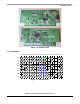
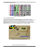
Figure 1-5. Multimedia Key Matrix
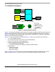
1.4.2 In-Circuit Programming
J3 and J7 contain all the signals for the MC68HC908JB8 to enter monitor mode for In-Circuit
Programming. The ICP requires J3 and J7 to be connected with a cable to the ICP adaptor board, which
is plugged-into the M68HC08 Serial Programmer (M68SPGRM08) (see
Figure 1-6). Running the
MCUScribe software on the PC allows erase, programming and verification of the firmware in the
MC68HC908JB8. The communication baud rate is determined by the jumper setting of J3 of the ICP
adaptor board. Connect pins 1 and 2 of J3 for 9600bps and pins 2 and 3 for 19200bps.
Figure 1-6. In-Circuit Programming Connection