
User Manual

MIL-PRF-55310/10J
3
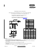
TABLE I. Dash numbers and operating characteristics.
1/ Maximum input current for no load condition. Actual configuration of TTL loads must be added to determine
power supply requirements.
2
/ A TTL unit load is defined as: 1.6 mA sink, 0.04 mA source, and 2 pF capacitance.
Frequency-voltage tolerance: 2 ppm maximum for a 10 percent change in supply voltage. Measurements taken
at reference temperature and operating temperature range end points.
Frequency aging: Measurements shall be taken at +70C 0.2C at intervals of not more than every 72 hours for a
minimum of 30 days (see table I).
5 ppm per year maximum
10 ppm per year maximum
0.7 ppm per 30 days 1.5 ppm per 30 days
1.5 ppm per 90 days 3 ppm per 90 days
Terminal strength: Method 211 of MIL-STD-202
, test condition C.
Applied force: 2 pounds each terminal for 10 seconds.
Bends: Five at 45 degrees each.
Frequency-environmental tolerance: Not applicable.
Vibration, sinusoidal: In accordance with MIL-PRF-55310
and method 204 of MIL-STD-202.
Nonoperating: Test condition D.
Operating: Not required.
Ambient pressure:
Nonoperating: In accordance with MIL-PRF-55310
.
Operating: Method 105 of MIL-STD-202
, test condition C.
Dash
num-
ber
Output
frequency
range
Input
current
max 1
/
at 5.25 V
1%
Pulse characteristics Initial
accuracy
ppm at
+23C
1C
Frequency
aging
ppm/year
after 30
days
Frequency-temperature
tolerance (ppm)
Rise
and
fall
times
max
Duty
cycle at
1.4 V
Load
2
/
-55C
to
+125C
-55C
to
+105C
-20C
to
+70C
A B C
01
1 kHz to
400 kHz
80 mA ns
15
percent
45 to 55
max
10 TTL
15
5
50
40
25
07 1 kHz to
400 kHz
80 mA 15 45 to 55 10 TTL
25 10 100 80 50
11 400 kHz
to 5 MHz
55 mA 15 45 to 55 10 TTL
15 5 50 40 25
17 400 kHz
to 5 MHz
55 mA 15 45 to 55 10 TTL
25 10 100 80 50
21 4 MHz to
20 MHz
40 mA 15 40 to 60 10 TTL
15 5 50 40 25
27 4 MHz to
20 MHz
40 mA 15 40 to 60 10 TTL
25 10 100 80 50
31 20 MHz to
60 MHz
65 mA 5 40 to 60 6 TTL
15 5 50 40 25
37 20 MHz to
60 MHz
65 mA 5 40 to 60 6 TTL
25 10 100 80 50