Safety Precautions The lightning flash with arrowhead symbol, within an equilateral triangle, is intended to alert the user to the presence of insulated dangerous Voltage within the product’s enclosure that may be sufficient magnitude to constitute risk of electrical shock. The exclamation point within an equilateral triangle is intended to alert the user to the presence of important operation and maintenance (servicing) instructions in the literature accompanying the appliance.
Before reading this document 1. This document is intended for both the administrator and users of this stand alone DVR Model. 2.This manual contains information for configuring, managing and using this stand alone DVR Model. 3. To prevent fire or electrical shock, do not expose the product to heat or moisture. 4. Be sure to read this manual before using this stand alone DVR Model. 5. For questions and technical assistance of this product, contact Q-see.
CONTENTS 1. FEATURES AND FUNCTIONS………………….………………………………….…..6 2. DESCRIPTION OF FRONT PANEL.…………………………………..……….7 2.1. RECORD/PLAYBACK CONTROL BUTTONS.………………..…….……………7 2.2. FUNCTION CONTROL BUTTONS.………………..………………………………8 2.3 CHANNEL SELECT BUTTONS.………………..……………………..……………9 3. REAR PANEL AND SYSTEM CONNECTIONS…..…………………………………10 3.1. BACK PANEL CONNECTIONS.…………………………………………………10 3.2. VIDEO & AUDIO CONNECTIONS.………………………………………………10 3.3. ALARM CONNECTIONS.………………..…...……………………………………11 3.4. HARD DRIVE INSTALLATION.
6. QUICK USER GUIDELINES……………………………………………………………31 6.1. STARTING THE DVR………………………………………………………………31 6.2. TURNING OFF THE DVR…………………………………………………………32 6.3. MANUAL RECORDING……………………………………………………………32 6.4. ALARM RECORDING………………………………………………………………32 6.5. SCHEDULED RECORDING………………………………………………………33 6.6. PLAYBACK…………………………………………………………………………33 6.7. SEARCH PLAY……………………………………………………………………33 6.8. TIME SEARCH…………………………………………………………..…………34 6.9. EVENT SEARCH……………………………………………………………………34 6.10.
1. FEATURES AND FUNCTIONS z Video input: 16channels; Video output: 3channels. z Audio input: 4channels; Audio output: 2channels. z 16 alarm input and 1 relay alarm output. z Compression mode: MJPEG. z Supports network view. z Supports USB backup. z Compatible with NTSC and PAL format. z Supports zoom, auto function, watermark security. z Four levels of image quality: very high, high, normal, low. Record and playback frame rate is changeable for recording.
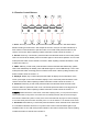
2. DESCRIPTION OF FRONT PANEL 2.1 Record/Playing Control Buttons 1. REC: this is the manual recording button. Press this button to record video to hard drive, press this button again, it will stop recording. Recording and stop will work simultaneously on 16 channels. This button doesn’t work in schedule mode. 2. PLAY: Press this button to start playing the video stored on the hard drive, Press this button again and it will stop playing. Play and stop will work simultaneously on 16 channels.
2.2 Function Control Buttons 1. Auto/1: Auto key, in shift mode, press this button and the DVR will be in auto dwell state, it dwells according to the time set in auto sequence set menu, and you can set the dwell time of each channel. Press this button to quit this mode. If not in shift mode press this button to see channel 1 full screen. When inputting numbers this button is used to enter the number “1”. 2.
8. ADD/7: Add key, press this button to see channel 7 full screen. When in system setup menu, this is an increase button. When inputting numbers this button is used to enter the number “7”. 9. DEC/8: Decrease key, press this button to see channel 8 full screen. When in system setup menu this is a decrease button. When inputting numbers this button is used to enter the number”8”. 10.
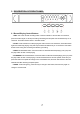
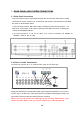
3. REAR PANEL AND SYSTEM CONNECTIONS 3.1 Back Panel Connections The power cable and input, output signal terminals are all on the back of the DVR, including connections to monitor, cameras, etc. The terminals and sockets on the back panel of the DVR are shown on the illustration below. 1. Video input CH1-CH16 2. Main Video output 3. Assistant monitor (Second monitor) 4. S- Video out 5. Audio input 6. Audio output 7. Ethernet port 8.USB port 9.power 10.debug port 11.
3.3 Alarm Connections The DVR can support up to 16-alarm inputs and 1 alarm output. Alarm input: there are two types of alarm input. 1. Voltage output (5V and 0V) A: If the sensor outputs high voltage (5V) normally and outputs low voltage when triggered (0V), then users must set the DVR as low voltage alarm. B: If the sensor outputs low voltage (0V) normally and outputs high voltage when triggered (5V), then users must set the DVR as high voltage alarm.
Alarm output: There are three alarm output pins, the status of these pin are illustrated below: Before Alarm After Alarm There is an example for alarm output connection 3.4 Hard Drive Installation Here are instructions to install the hard drive. Notice: If the DVR comes with a HDD pre-installed then skip the following steps. 1. Pull out the hard drive rack from 2. Open the top cover of the drawer. DVR 3. Connect the DATA cable & power cord. 4.
4.
Hold down the menu/search button on the keyboard or press the remote control to enter the Setup Main Menu. This will show the password input box. If you enter the wrong password 3 times, then you can’t enter the setup menu.
5.2 SYSTEM SETUP Press “ENTER” button to enter sub menu PLAY REPEAT: Set the Playback Repeat option VIDEO SYSTEM: Set video format of the DVR as NTSC or PAL BUZZER SOUND: Set the Buzzer On/Off 5.2.1 TIME/DATA SETUP Set the date and time.
5.2.2 HDD FORMAT SETUP Use to format the hard drive. Select “YES”, to format the hard drive and all video on the HDD will be erased. 5.2.3 FACTORY RESET If you select Factory Reset; the DVR will reset to factory default settings.
5.2.4 Change Password Move the cursor to CHANGE PASSWORD and press the Enter button, the Change Password window will appear. Password Level: There are different levels of password security SETUP: If set to “YES” you have to input password to enter menu. SYSTEM: If set to “YES” you have to input password to boot the DVR. ALWAYS: If set to “YES” you have to input password to enter all operations.
5.2.5 Firmware Update Move the cursor moves to FIRMWARE UPDATE and press the Enter button, the firmware update window will appear. Update Method: There are two methods to update the DVR’s firmware, USB (for USB flash drives) and Network (not supported on this model) USB update: create a new folder called “firmware” in the USB flash drive’s root directory, copy the update file to the folder, and plug in the USB flash drive. Enter the Firmware Update menu, select Update Start and press the Enter button.
5.3 DISPLAY SETUP BOUND COLOR: Set the Color of Video Boundary (BLACK / WHITE / GRAY). BLANK COLOR: Set the Background Color of Lost Video screen (BLACK / WHITE). 5.3.1 CAMERA NAME SETUP Move the cursor to Camera Name and press the Enter button, the Camera Name Setup window will appear as shown below: Press the up or down buttons to select channels, press the Enter button to change the channel name.
Each channel’s name is a combination of six to eight characters. Press UP or DOWN buttons to select each character, press LEFT or RIGHT buttons to modify each character, and then press the Enter button to save this name. DISPLAY: if Display is set to “OFF” the channel’s name will not display on the screen. 5.3.2 COLOR SETUP Move the cursor to color set and press the “ENTER” button, the Color Setup window will appear, which is illustrated below.
5.3.3. AUTO SEQUENCE SETUP Set the Display Time of Auto Sequence. Press “ENTER” button, the auto sequence setup window will appear, which is illustrated below: Set the time of the selected channel. Time can be set in a range from 0 to 99 seconds. 5.4 RECORD SETUP OVER WRITE: if set to “YES” the DVR will automatically overwrite the HDD from the beginning when the HDD is full. If set to “NO” the DVR will stop recording automatically when the HDD is full.
REC QUALITY: There are four video quality settings: VERY LOW, LOW, NORMAL, HIGH and VERY HIGH. The higher the video quality, the clearer the images when you playback. The lower the video quality the more space you can save on the hard drive. RESOLUTION: The record picture size of the DVR. There are two modes: CIF (360) and Field (720), default is CIF. In Field mode the record picture is twice as large as it is in CIF mode.
5.4.2 RECORD CHANNEL SETUP Move the cursor to REC CH Set and press the “ENTER” button. The REC CH setup window will appear. This option is only available in Field mode. Press the up and down buttons to select a channel, then press left or right buttons to change the setting. If the channel setting is OFF this channel will not be recorded in recording mode. If the resolution is set to CIF mode the REC CH Setup window is not accessible. Set Record ON/OFF for the selected channels. 5.
NETWORK ENV: the DVR has three types of different network environments: LOCAL, EXTER_LAN, EXTER_WAN. If on a local network select LOCAL. For internet access choose EXTER_LAN If the internet condition is not very good select EXTER_WAN. VIDEO PORT: the port the DVR uses to transmit video. COMMAND PORT: the port the DVR uses to transmit commands. If you change the VIDEO PORT, COMMAND PORT, or MAC address you have to restart the DVR to use the “PC Viewer” software.
5.5.2. MAC ADDRESS SETUP Move the cursor to MAC set then press the “ENTER” button. The MAC set window will appear which is illustrated below: If you have more than one DVR in a local area network you have to set each DVR to have an exclusive MAC address, but remember that you have only one chance to modify the MAC address, once you have changed the MAC address this menu will no longer appear. 5.5.
5.5.4 ACCESSING THE DVR FROM A REMOTE COMPUTER To access from a remote computer, after you complete the above steps you need to forward ports 5000 and 5001 on the router the DVR is attached to, to the IP address of the DVR. How you would do this depends on the brand and model number of your router. You can go to www.portforward.com to get instructions on how to forward ports on most popular routers. This information should also be available in your router’s manual.
MOTION ENABLE: motion alarm switch, it can be set to on or off. If users set it to off the DVR’s motion alarm will be ignored. If it is set to on then the DVR’s motion detection will be enabled. MOTION LEVEL: motion detection sensitivity level, if the figure in the picture is small please set to high or very high, the default is normal. BUZZER TIME: buzzer sound time when there is a sensor or motion alarm.
Notice: The above suggestions are a guide based on testing in a general environment. You will need to select the best settings according to the actual operation environment you are covering. Try different settings until you get the desired motion detection result. 5.6.2 MOTION AREA SET Move the cursor to Motion Area Set, then press the Enter button, and the area setup window will appear. Press the UP, DOWN, LEFT, RIGHT buttons to move the cursor and press the Enter button to change from detection ON to OFF.
5.7 SCHEDULE SETUP Move the cursor moves to Schedule Set and press the Enter button. The schedule setup window will appear listing the days of the week. Select a day and press the Enter button and the below window will be displayed. You can setup a recording schedule for each day by using this setup window. Please note: Military time must be used. You can setup 7 time periods for each day.
There are two types of backup mode: STILL and MOVIE, in STILL mode you can backup Pictures and in MOVIE mode you can backup video files. 5.
5.10 PTZ SETUP Set the right protocol, baud rate, and ID and you can control SPEED DOME cameras through the DVR. Move the cursor to Protocol Set, then press the “ENTER” button, the protocol set window will appear which is illustrated below. Press up or down buttons to move the cursor and press right or left buttons to change the value. CHANNEL SEL: Select the video channel that is connected to the speed dome that you want to control. BAUDRATE: Range is from 1200bps to 19200bps.The default is 2400bps.
6.2 TURNING OFF THE DVR You normally only turn off the machine when you want to shut the system down. Do not turn off the machine while playing or setting the system up. Especially do not to turn off the DVR while recording. Press the recording button to stop recording or press the play button to stop playing, or exit from system setup menu, then turn off the power by unplugging the DVR.
6.5 SCHEDULED RECORDING Scheduled recording starts and stops recording automatically according to the pre-arranged time period. To start scheduled recording, after setting up the record schedule you must press down the schedule button on the front panel to turn the schedule on. While pressing down this button the schedule symbol “S” will display on the screen. For instructions on setting up a schedule refer to 5.7 Schedule Set.
6.8 TIME SEARCH Move the cursor to Time Search, then press “ENTER” button. The time search window will appear as illustrated below: A red block during a time period means there is video at that time Press left and right buttons to move the cursor among year, month, day, hour and minute. If you select the year and press the “ENTER” button you can select month and then day and hour. Press ADD and DEC button to modify the time.
time recording, NETWORK means network recording Press up and down buttons to move the cursor among the event lists, press left and right buttons to see previous or next page, press the “ENTER” button to play the file you select. Press search button to return to Search Play menu. If you want to change the search from MASTER HDD to SLAVE HDD just press the mode key which will display the screen below, then press the “ENTER” key to change. Press menu key to quit. 6.
6.11 USB BACKUP To use this function the first step is to format the USB device with “FAT” system on your computer, the DVR doesn’t support “FAT32” file system. Plug in the USB flash drive, go to the Backup set menu, check to verify if the flash drive was detected or not, and if there is enough free space on the flash drive for the file or files you want to backup. Select the backup mode then quit the menu setup.
6.13 ZOOM FEATURE (For use with PTZ speed dome cameras) In shift mode press the zoom button or press the zoom button on the remote control, the DVR will be in zoom mode which is illustrated below: Press up, down, left or right buttons to move the zoom area and then press the “ENTER” button to zoom. Press the zoom button again to cancel zoom operation. 6.14 PTZ OPERATION This DVR can control speed domes, which are connected to the DVR.
6.15 INFORMATION DISPLAY In shift mode press the display button, the main information of the DVR will display on screen. HDD SIZE: the size of the hard drive HDD USED: the amount of used space on the hard drive. HDD READ: current HDD address for playback OVERWRITE: overwrite time of the HDD NETWORK IP: IP address of the DVR. REC LIST: number of record lists EVENT LIST: number of event lists REC OVER: record list overwrite or not EVENT OVER: event list overwrite or not.
7. Using the PC VIEWER SOFTWARE Using the PC Viewer software you can view the DVR over a network or the Internet. You can also view and backup the video information on the HDD to a computer. When you open the software you will see the window below: 7.1 SETTINGS When you click button you will see the window below: enter the IP address of the DVR for local access, or the internet IP address of the router for internet access, and click the “OK” button.
7.2 CONNECTING TO DVR Pressing the button will display the login box. 7.3 LIVE PLAY Once you have connected start the video by clicking on the play 40 button.
7.4 PLAYBACK Click the “Playback” button and the net search window will display. First you have to select the HDD of the DVR (first picture below). Click the “Get record list” or “Get event list”. If the DVR has record list you can see the second window below: Double click a file on the record list and you will playback the video. The event list operation is the same as record list operation 7.5 SCANDISK Connect the HDD that is used in the DVR to a PC and then select Scandisk.
7.6 FILE PLAY Press the “File Play” button; you will see the picture below. Press the “open” button to play the video file on the computer. < File play Menu> 1. By pressing this button you can record the video from the DVR to the computer. 2. Pressing this button will open the box below to save files as AVI. 3. You press this button to start & stop playing video from the DVR. 4. By pressing this button you can record files from the DVR to the computer’s HDD. 7.
7.8 Save to PC Hard Drive To record the video stream to your PC’s HDD , just click" DVR" button and the video stream will be saved in the directory that you set (the default directory is c:\DVR\) Notice: to play the file saved to DVR just click "FilePlay" tab to open it.
8. SPECIFICATIONS 8.1 DVR Item Specification Compressed picture M-JPEG Video signal NTSC/PAL Video input Conposite:1.0Vp-p/75Ω,BNC×8/16 Video output Conposite:1.
9. TROUBLE SHOOTING GUIDE Q. What kind of cameraS should I buy for this DVR? A. Any BNC or RCA interface indoor/outdoor/infrared camera will work with the DVR. It doesn’t matter whether it’s a color or black/white camera. However web cameras that require a USB interface are not compatible with the DVR. Q. What kind of alarm device should I buy for DVR? A. Most sound alarms are compatible with our DVR. Q. I can’t turn on DVR. A.
Q. Why can’t I access Time/Date Set, HDD Format Set, Record Set menu? A. Please stop recording or playing back before you access these menu. Q. Why can’t I access Network Set menu? A. Please quit the connection of the PC Viewer software from the network or Internet before you access Network Set menu. Q. I press the record button but the DVR does not start recording, why? A.
10. RECORDING TIME TABLE Rec rate frame/sec Picture Quality Resolution Recording time 60 fps Very high 720 47 hours 60 fps Low 720 125 hours 120 fps Normal 360 47 hours 1 fps Normal 720 4500 hours Notice: The above figures are from our tests with a 250GB hard disk and are for users’ reference. Q-SEE PRODUCT WARRANTY Thank you for choosing our products.
Customer Information Card User’s Name Mr./Mrs. Company Name Postal Address Postal code Phone Number E-mail Model Number of Product Serial Number of Product Purchase Date Distributor If you have questions: Contact Us: Mailing Address: DPS Inc. 8015 E. Crystal Dr Anaheim, CA 92807 Customer Service: Phone: 877-998-3440 x 538 Email: cs@dpsi-usa.com Website: http://www.q-see.com Tech Support: Phone: 877-998-3440 x 539 Email: ts@dpsi-usa.
The material in this document is the intellectual property of our company. No part of this manual may be reproduced, copied, translated, transmitted, or published in any form or by any means without our company’s prior written permission. 1. Our products are under continual improvement and we reserve the right to make changes without notice, therefore no guarantee is given as to the correctness of its contents. 2. We do not accept any responsibility for any harm caused by using our product. 3.