GigWorks™ MKII-16 Switch Model MKII-BASE16 Installer’s/User’s Manual Publication No. 59003-01 Rev.
Ancor Communications Incorporated 6130 Blue Circle Drive Minnetonka, MN 55343 (612) 932-4000 Release Number 01, Revision A ( December, 1998) This release obsoletes all previous releases.
Table Of Contents Preface 1 1 2 2 3 3 6 9 How to Use This Manual Intended Audience Related Materials Ancor Customer Service Safety Notices Communications Statements Laser Safety Information Accessible Parts 1.
Table Of Contents 3.
Table Of Contents 3-54 3-55 3-56 3-57 Community Types Operation Types Management Information Bases (MIBs) Configuring SNMP 4. Diagnostics/Troubleshooting 4-1 4-1 4-5 4-5 4-7 4-7 4-7 4-7 4-12 4-12 4-13 4-15 Introduction Power Supply Troubleshooting Power-On-Self-Test (POST) Overview Heartbeat LED Blink Patterns Normal (all pass) Failure Blink Patterns Test/Failure Descriptions Continuous Test Overview Procedure Fiber Continuity Tests 5.
Table Of Contents Appendix C: Chassis Switch Panel C-1 C-2 C-2 C-2 C-3 C-4 Chassis Switch Panel Reset Force Prom Mode Watch Dog Timer Disable Test Mode Chassis#, Fabric#, Stage#, and Area# Configuration Switches List Of Figures 1-1 1-6 1-7 1-10 Figure 1-1 Figure 1-2 Figure 1-3 Figure 1-4 GigWorks MKII-16 Switch Model MKII-BASE16 Chassis Front Typical GBIC Chassis Back 2-2 2-3 2-11 Figure 2-1 Figure 2-2 Figure 2-3 GigWorks MKII-16 Switch Model MKII-BASE16 Chassis Components Cabinet Mounting Bracket Ca
Preface How to Use This Manual This manual has five sections and three appendixes: • Section 1 is an overview of the GigWorks™ MKII-16 Switch Model MKIIBASE16. It describes indicator lights and all user controls and connections. • Section 2 explains how to install the Switch. • Section 3 contains Switch Management information. • Section 4 contains troubleshooting procedures, explains the Power On Self Test (POST), and Continuous Test.
Preface Related Materials The following manuals and materials are referenced in the text and/or provide additional information. • The following Fibre Channel Standards: Fibre Channel Physical and Signaling Interface (FC-PH) ANSI X3.2301994. Arbitrated Loop (FC-AL) ANSI X3.272-1996.
Communications Statements Safety Notices A Danger notice indicates the presence of a hazard that has the potential of causing death or serious personal injury. Danger notices appear on the following pages: 2-5, 2-6, and 5-6 A Warning notice indicates the presence of a hazard that has the potential of causing moderate or minor personal injury. There are no Warning notices in this manual. A Caution notice indicates the presence of a hazard that has the potential of causing damage to the equipment.
Communications Statements radioélectriques por les appareils numériques, telles que prescrites par le Réglement sur le brouillage radioélectrique établi par le ministère des Communications du Canada. L'exploitation faite en milieu résidentiel peut entraîner le brouillage des réceptions radio et télé, ce qui obligerait le propriétaire ou l'opérateur à prendre les dispositions nécwssaires pour en éliminer les causes.
Communications Statements VCCI Class A Statement Translation: This is a Class A product based on the standard of the Voluntary Control Council For Interference by Information Technology Equipment (VCCI). If this equipment is used in a domestic environment, radio disturbance may arise. When such trouble occurs, the user may be required to take corrective actions. GigWorks MKII-16 Switch Model MKII-BASE16 Installer's/User's Manual 59003-01 Rev.
Laser Safety Information Laser Safety Information The GigWorks 1062/16 MKII Switch may use Class 1 lasers to communicate over the fiber optic conductors. The U.S. Department of Health and Human Services (DHHS) does not consider Class 1 lasers to be hazardous. The International Electrotechnical Commission (IEC) requires labeling information that states that the lasers are Class 1.
Laser Safety Information Optical GBICs Each optical GBIC is a single communications port. Each communications port consists of a transmitter and receiver optical subassembly.
Laser Safety Information Labeling Requirements There are no caution or danger labels required for use of the optical GBIC since it is a Class 1 laser component assembly. Within the U.S., the only laser safety label required is the certification label that already appears on the plastic retainer of the optical GBIC assembly. Outside of the U.S.
Accessible Parts Accessible Parts The only Field Replaceable Units (FRUs) in the GigWorks MKII-16 Switch Model MKII-BASE16 are: • fuses associated with the AC power input, • power supply(s), and • interfaces to the interconnection media called GBICs. Other than these FRUs, there are no accessible parts in the Switch chassis. Removal of the top of the Switch chassis will void the warranty. Refer to Section 4 (Removal Replacement Procedures) for more information.
10 Table Of Contents GigWorks MKII-16 Switch Model MKII-BASE16 59003-01 Rev.
Section 1 GigWorks™ MKII-16 Switch Model MKII-BASE16 General Description GigWorks™ MKII-16 Switch Model MKII-BASE16 General Description The Switch is the Fabric component of a Fibre Channel compliant network. Figure 1-1 is an illustration of the Switch. CO MM UN ICA TIO NS , INC . Figure 1-1 GigWorks MKII-16 Switch The Switch uses a two-dimensional switching architecture consisting of spacedivision and time-division interconnection techniques to implement the Fibre Channel (FC) fabric.
General Description • All ports used as F_Ports support Class 1, Class 2, Class 3, and Intermix Fibre Channel service. Refer to the Reference Information appendix for more information. • All ports support the maximum Fibre Channel frame size (2148 bytes) for all classes of Fibre Channel service. • All ports used as FL_Ports support Class 2, and Class 3 Fibre Channel service. Refer to the Reference Information appendix for more information.
General Description information about the Web-based Switch management application.
General Description of these Broadcast Zones. A port will broadcast to all ports in the same Broadcast Zone (or zones) in-which the port is defined. If Hard Zones are enabled, Broadcast Zones may not cross the defined Hard Zone boundaries. • • Name Server Zones allow the division of the fabric into as many as 16 zones that define which ports receive Name Server information. A particular port may be defined in one or more of these Broadcast Zones.
General Description ordered from Ancor) be placed on each port populated with a GBIC so that the GBICs may be tested. Refer to the LED paragraphs later in this section and the Continuous Test paragraphs in the Troubleshooting section. • LEDs indicate the status of the Switch and each port. Refer to the Front Panel LED paragraphs later in this section. • The Switch contains an Ethernet connector that provides a connection to a management station.
General Description Fibre Channel Port* All ports shown on this drawing are served by GBICs with SC -Type fiber optic connectors. RX TX Heartbeat LED (Yellow) Over Temperature LED (Red) Port number Power Supply Fail LED (Red) Traffic LED (Yellow) 8 Logic Power Good LED (Green) Logged-In LED (Green) Power Button WORKS™ MKII COMMUNICATIONS, INC.
General Description Currently, the following GBICs are certified for use: Short-wavelength fiber optic GBICs 100-M5-SL-I or 100-M6-SL-I with Open Fiber Control (OFC) support connection to legacy 1062 megabaud Fibre Channel networks. The Optical Link Modules (OLMs) used by many legacy Fibre Channel transmitters and receivers contain an internal OFC system. The OFC is a safety interlock that detects when the optical link has been interrupted and shuts down the laser.
General Description Front Panel Controls Power Button Figure 1-2 shows the location of the Power Button. The Power Button is protected by a clear plastic cover that must be flipped UP in order to reach the button. The Power button is an alternate-action switch (press it to turn it on and it stays depressed, press it again to turn it off and the button releases). When you press the Power button and turn it ON, you enable the logic voltages to leave the Power Supply(s) and enter the Switch logic.
General Description Following a normal power-up with the Continuous Test button in the OFF position, the Heartbeat LED blinks about once per second to indicate that the Switch passed the POSTs and the internal Switch processor is running. Refer to Section 3 (Diagnostics/Troubleshooting) for more information about Heartbeat LED error codes. Logic Power Good (Green) This LED is ON when any Power Supply is delivering power within normal limits to the Switch logic (the Power Button must also be depressed).
General Description time or several times over a short period of time when they are powered up. If the Switch was not operable at that time, it would miss this login attempt and the attached node may give up trying and require rebooting after the Switch becomes operable. Port Activity LED (Yellow) Each port has its own Port Activity LED. The Port Activity LED for a particular port is ON when Class 1, 2, or 3 frames are entering or leaving the port. The Switch turns the LED ON for 50 msec.
General Description An Input Fuse Holder is incorporated into the AC Input Power Connector assembly. It holds two input fuses. Refer to Section 3 for Troubleshooting information, Section 4 for Removal Replacement, and the Reference Information appendix for fuse size. Power Supply(s) The chassis has bays for two power supplies. When there is only one supply, it can operate from either bay and the unused bay is covered with a plate. The fan on a Power Supply also furnishes cooling for the Switch chassis.
General Description When the overheated power supply cools down, the power supply will attempt to place itself back in service. If the cause for the overheating condition is still present, the power supply will eventually overheat again and the shutdown process will repeat. During the periods where both power supplies are operating, the Power Supply Fail LED on the front of the chassis will turn OFF. The Power Supply Fail LED will only be ON when one of the two power supplies is actually failing.
Section 2 Installation Installation Note: This manual covers the installation and cabling of single-stage Switch chassis only. There are seven basic steps required to install the Switch. 1. 2. 3. 4. 5. 6. 7. Unpack Place or Mount the Equipment Apply the IEC Laser Safety Label (If the installation is in Europe) Install the GBICs Connect the Switch to AC power Check the Power-On-Self-Test (POST) results Cable Adapters to the Switch a. Unpack the Switch from the carton.
Installation 2. Place or Mount the Equipment The Switch may be placed on a flat surface and stacked or mounted in a 19” EIA rack. The Switch comes physically configured for placing on a flat surface. That is, it comes with rubber feet on the bottom and side-fillers installed. Refer to Figure 2-1. Side Fillers (2) COM MUN ICA TIO NS, INC .
Installation Philips-head screws, one in each hole in the Side Fillers. c. Mount the Brackets. Refer to Figure 2-2. The Switch is shipped with a package containing cabinet mounting brackets and screws. You may mount these brackets on the front corners of the chassis or the back corners depending on whether you want the Switch facing the back or front of the cabinet. Note: If you mount the Switch in a 19” EIA rack, it must be installed on rails or on a shelf. d.
Installation 3. Apply the IEC Class 1 Laser Information Label (If the installation is in Europe) If the installation is in Europe, IEC regulations require that a Class 1 laser information label be placed where it is clearly visible whenever access to the optical ports is possible. The drawing below pictures the label.
Installation 5. Connect to AC Power Danger: An electrical outlet that is not correctly wired could place hazardous voltage on metal parts of the Switch chassis. It is the responsibility of the customer to ensure that the outlet is correctly wired and grounded to prevent electrical shock. Danger: Une prise électrique dont les fils sont mal branchés peut créer une tension dangereuse dans les pièces métalliques du châssis Switch.
Installation Danger: This product is supplied with a 3-wire power cable and plug for the user’s safety. Use this power cable in conjunction with a properly grounded outlet to avoid electrical shock. You may require a different power cable in some countries because the plug on the cable supplied with the equipment will not fit your electrical outlet. In this case you must supply your own power cable.
Installation Refer to Appendix A in this manual for Switch power requirements. a. Connect the power cable to the back of the chassis. b. Connect the other end of the power cable to a 3 wire, grounded, AC outlet that delivers power in accordance with the power requirements specified in Appendix A. Note: Following the connection of AC power to the chassis, the fans start turning immediately but power is not applied to the logic until the Power button is pressed. c. Press the Power Button.
Installation Step 7 unless the POST passed. 7. Cable N or NL_Port Adapters to the Switch Ports All 16 ports on the Switch may connect to N_Ports. Ports 1, 2, 5, 6, 9, 10, 13, and 14 may connect to NL_Ports or N_Ports. The type of media used (fiber optic cable or copper) depends on the type of N or NL_Port adapters used and the type of GBICs used in the Switch. You may populate the Switch with any assortment of approved GBICs appropriate for your interconnection media type.
Installation Incorrect Cabling Cabling connected incorrectly will not damage the GBICs or the Switch. N_Port Connections Connect Fiber Channel N_Ports to F_Ports on the Switch. All 16 ports on the Switch will function as F_Ports. The Switch will automatically discover which N_Port is connected to which F_Port during Fibre Channel Login process as each N_Port is powered up. Fiber Optic Connections Note in Figure 2-3 that each N_Port connects to the switch with a pair of connectors.
Installation Most NL_Port connections to the Switch are via Hubs or directly to storage devices such as JBODs and disc arrays. Connect the transmit SC fiber optic connector on the FL_Port to the receive SC fiber optic connector on the NL_Port. Connect the receive SC fiber optic connector on the FL_Port to the transmit SC fiber optic connector on the NL_Port. In some cases you may need to connect a loop of NL_Ports to the Switch without the use of a Hub.
Installation N_Port Tx Rx Fiber optic connections WORKS™ MKII COMMUNICATIONS, INC.
Installation Operating the Switch The Continuous Test button on the front of the Switch chassis and the switches on the Chassis Switch Panel on the back of the Switch chassis are the only operational controls. Place the Continuous Test button in the IN position for normal operation. The Test mode switches must be set to 0 (POST). Refer to the Chassis Switch Panel paragraphs in Section 1 of this manual. The default is 0.
Section 3 Switch Management Introduction The Switch supports management through: • the Windows NT™ or Windows 95™-based GigWorks MKII Switch Utilities, • a Trivial File Transfer Protocol (TFTP) server, and • a built-in SNMP Agent. • Optionally, the GigWorks MKII Switch Web-Based Management Interface application is also available. This management interface is a Web-based (Java) application. The Switch Utilities require an Ethernet connection to each managed chassis.
Introduction • Configure the desired Port State and read the actual Port State On Line Off Line Test Failure (Read only) • Read the status of each port including: • 3-2 • Port Type for each fabric port F_Port FL_Port T_Port (Trunk ports interconnect chassis in a multi-stage fabric.
Introduction define the area of Broadcasts. A particular port may be placed in one or more of these Broadcast Zones. A port will broadcast to all ports in the same Broadcast Zone (or zones) in-which the port is defined. If Hard Zones are enabled, Broadcast Zones may not cross the defined Hard Zone boundaries. • Name Server Zones allow the division of the fabric into as many as 16 zones that define which ports receive Name Server information.
Ethernet Cabling Ethernet Cabling The Switch is managed through the use of a customer-supplied management station connected to the Switch via 10BASE-T Ethernet. Figure 3-1 shows the location of the Switch Management connector and the cable wiring. The Ethernet connection is hot-pluggable (that is, you may connect the Ethernet cable with power applied to the Switch).
Configuring the Switch Ethernet Port Configuring the Switch Ethernet Port Note: The Switch cannot be managed through the Ethernet port without the management station knowing the IP address of the Switch. If the IP configuration of the Switch is lost, the Switch can be reset in PROM mode. In Prom mode, the Switch always uses the default management parameters, not the parameters defined in the configuration file. In this way, the Switch can always be returned to a 10.0.0.x network and reconfigured.
Configuring the Switch Ethernet Port IP Address. When all parameters have been set correctly, click the Set Parameters Button to set the values on the Switch chassis. The new values will be saved on the Switch, and will take effect when the Switch is powered down and back up (re-booted). You may also force the Switch to begin using the new values immediately by clicking the Reset the Ancor GigWorks MKII Management Only Button.
Managing the Switch Using the GigWorks MKII Switch Utilities Managing the Switch Using the GigWorks MKII Switch Utilities The Switch Utilities allow you to manage the Switch through its Ethernet interface. Loading the Switch Utilities In order to run the Switch Utilities, you must provide an IBM®, or compatible, PC with an Ethernet output, running Windows NT™ version 4.0 or Windows 95™ (or later), and an Ethernet cable.
Switch Utilities Switches come configured from the factory with the default address 10.0.0.1.) 3. Use the Setup Tab to read the UART statistics to make sure the Utilities can connect to the Switch. Using the Switch Utilities The user interface to the Switch Utilities is a standard Windows™-type interface structured like a set of tabbed file folders (Refer to Figure 3-2). Use the cursor to click on any tab and the screen will display a dialog box for that tab.
Switch Utilities each tab. The system saves only the contents of the data window of each tab. That is, it does not save such things as button settings. Tabs that do not contain any data, such as the tab used to load new control code into Flash memory, have the Save command disabled. File>Save As The Save As command operates on a tab-by-tab basis. That is, if you perform a Save As command while the Setup tab is selected, the system saves the contents of the data window of only the Setup tab.
Switch Utilities — Management Information Management Information Figure 3-2 Management Information Tab Refer to Figure 3-2. The Management Information tab enables you to display all the managed objects provided by the Switch. These objects consist of 11 tables, divided into 5 functional groups. These groups are: • fcFeConfig — Configuration • fcFeOp — Operation • fcFeError — Error • anMkiiAccounting — Accounting • fcFeCap — Capabilities Each group has one or more tables associated with it.
Switch Utilities — Management Information in the Ancor Web-site (www.Ancor.com).
Switch Utilities — Management Information Management Information Tab Controls/Windows Port Field Enter the Fibre Channel port number for-which you want to read the SNMP information. The range for a 16-port Switch is 1-16. The range for an 8-port Switch is 1-8. Group Select List Select the Group that contains the desired table. You may select All or any one group from the Group List. Table Select List Select the desired table. You may select All or any one table from the Table List.
Switch Utilities — Flash Flash Figure 3-3 Flash Tab Refer to Figure 3-3. The Flash tab enables you to load new control code into the Switch’s Flash memory and also to command the Switch to perform a Reset operation. In order to load new Flash Code, you must first connect the switch directly to the PC used as a management Station using a “Cross-Over” Cable. In the event that your Flash memory requires an update, Ancor Communications will supply you with a binary Flash update file.
Switch Utilities — Flash new Flash code: You may place the cursor in the Flash File Name box and type it, or you may click the Select button. Clicking the Select button produces a standard Windows operating system dialog box that allows you to open the Flash update binary file. When you open the Flash update file, its path/name will appear in the Flash File Name box as you would have typed it.
Switch Utilities — Versions Versions Figure 3-4 Versions Tab Refer to Figure 3-4. The Version tab enables you to display and log the Switch hardware and software version numbers. For a 16-port Switch it also displays the settings of the switches on the Chassis Switch Panel which is located on the back of the 16-port Switch chassis and read by the Switch at power-up. Windows in the Version tab display these numbers. World Wide Name This number is the unique number of the Switch chassis.
Switch Utilities — Versions memory. This number is loaded as part of the Flash code. Therefore, this number could change following a Flash load. Prom Software Version: This is the version number of the control code in PROM. This number is read from the PROM. Therefore, this number could change following a PROM change. Hardware Version (PCB.ASIC): The number on the left side of the period is the version number of the board in the Switch.
Switch Utilities — Diagnostics Trace Diagnostics Trace Diagnostics Trace Overview The Diagnostics Trace tab allows Ancor service personnel to follow the progress of selected operations as they proceed through the Switch. This tab is included in the Switch Utilities for the customer because at some point, if you are experiencing problems, an Ancor Service engineer may ask you to perform a Diagnostics Trace, read the results, and send them back to the factory.
Switch Utilities — Diagnostics Trace Figure 3-5 Diagnostics Trace Tab (Enables) Controls are divided into two groups, Enables and Display. Diagnostics Enable Controls Refer to Figure 3-5. The Enables controls allow you to read and display the current list of Diagnostics Trace functions from the Switch. The display shows which functions are enabled and which are disabled.
Switch Utilities — Diagnostics Trace Enables None Button Deselect (remove the highlight from) all Diagnostics Trace functions. You may deselect Diagnostics Trace functions one at a time by checking individual selected (highlighted) functions in the list. Enables Apply Button Applies the list to the Switch and activates the Diagnostics Trace functions that are selected in the list and deactivates any that were active and are now not highlighted in the list.
Switch Utilities — Diagnostics Trace Display Offset Box The Offset is a hexadecimal address offset into the 4K circular Diagnostics Trace Buffer. Display Quantity Box The Quantity is the hexadecimal number of lines/addresses you want to read. Display Read Button Press the Read button to read the number of Diagnostics Trace Buffer addresses/lines specified by the Quantity box, starting at the address specified by the Offset box and display them in the Display Information Display Window.
Switch Utilities — Setup Setup Figure 3-7 Setup Tab Refer to Figure 3-7. The Setup tab enables you to set up the connection between the Ethernet port on the PC and the Ethernet port on the Switch and to track the communication that takes place over this connection. The Setup tab also enables you to read and display UART statistics. Ethernet Port Radio Button The Ethernet Port Radio Button, when selected, causes the Utilities to communicate to the Switch through the Ethernet port on the PC.
Switch Utilities — Setup UDP Port # Box This is the UDP Port Number the Utilities application uses to communicate with the proper application in the Switch. The default port number is 5000. Use Sequence Checkbox. For future use. Serial Port Radio Button (Legacy Switches only) Press the Serial Port Radio Button to enable communication via the legacy Switch RS-232 port. and the local PC Serial Port.
Switch Utilities — Chassis Configuration Chassis Configuration Figure 3-8 Chassis Configuration Tab Refer to Figure 3-8. The Chassis Configuration tab enables you to assign or modify the Fabric ID, the Chassis Number, the Stage Type, Fibre Channel timeouts for the chassis, and the Administrative State of each port on the chassis. It also allows you to read the Operational State of each port on the chassis. Fabric ID Place the cursor in the Fabric ID box and type a fabric number.
Switch Utilities — Chassis Configuration both numbered beginning with 00. Press the Apply button to apply the Chassis Number to the chassis. Stage Type Radio Buttons Any MKII Switch chassis can function as either of two Stage types. These are an Input-Output/Transfer chassis (IO/T) or a Cross-Connect chassis (CC). Refer to the fabric descriptions below for information about the two chassis types. Refer also to the MKII Switch Multi-Stage Installer’s/User’s manual.
Switch Utilities — Chassis Configuration Administration/Operation States The Administration State is the state you would like the chassis and each of its Ports to be in. The Operational State is the state they are actually in. You may configure the chassis and each of its ports to be ON LINE or OFF LINE or in Test. Refresh Button The Refresh button reads data from the Chassis and displays it.
Switch Utilities — Port Status Port Status Figure 3-9 Port Status Tab Refer to Figure 3-9. The Port Status tab enables you to find the status of all ports on the Switch and any connected Loop devices and to control the Mode of the port (F or FL) and to enable or bypass Loop devices. The Port Status screen has two windows, Port Status and Loop Status. Each window has three buttons for control. A description of these windows and their associated buttons follows.
Switch Utilities — Port Status Port Field: The Port field lists each port on the Switch. Status Field: The Status field tells whether a port is Online or Offline. Mode Field: The Mode field tells whether a port is operating as an F_Port, an FL_Port, or a T_Port (Trunk Port in a multi-stage fabric). Login Status Field: The Login Status field indicates whether or not a port is Logged in. AL-Enabled Field: The AL-Enabled field is user controlled.
Switch Utilities — Port Status depends on the capabilities of the loop devices and what has happened since the loop was last initialized. Generally, when a loop is initialized, all Enabled devices that successfully initialize receive an AL_PA. Thus the Switch knows of their existence and can report that fact to the Switch Utilities. There may be devices on the loop that are not powered up or are in Bypass mode. These devices will not receive AL-PAs and the Switch will not know of their existence.
Switch Utilities — Zoning Zoning Figure 3-10 Zoning Tab Zoning allows the user to divide the fabric ports into zones for more efficient and secure communication among functionally grouped nodes. There are three types of zones and a port may be defined in any or all of them. • Hard Zones follow physical boundaries within a Single-Stage Switch chassis and limit the communication of a port to only other ports in the same Hard Zone.
Switch Utilities — Zoning each zone is fabric-wide) that define which ports receive Name Server information. A particular port may be defined in one or more of these Name Server Zones. A port will receive Name Server information for all ports in the same Name Server Zone (or zones) in-which the port is defined. If Hard Zones are enabled, Name Server Zones may not cross the defined Hard Zone boundaries. Hard Zone Rules: 1. A Hard Zone is only valid if it is enabled. 2.
Switch Utilities — Zoning Broadcast Zone Rules: 1. A Broadcast Zone is only valid if it is enabled 2. If Broadcast Zones are used on a Single Stage Switch in-which Hard Zones are defined, the Broadcast Zones must not overlap Hard Zone boundaries. For example: If Hard Zoning in an 8-port Single Stage Switch places Port 6 in one zone and Port 7 in another zone, Broadcast Zoning must not include Ports 6 and 7 in the same zone. 3. Broadcast Zones operate fabric-wide (Single Stage or Multi-Stage). 4.
Switch Utilities — Zoning 6. All ports not defined as being part of any enabled Name Server Zone are Name Server Zone Orphans. Name Server Zone Orphans are all placed in the same Name Server Orphan zone. Zoning Screen Refer to Figure 3-10. The Zoning tab enables you to read the current zoning assignments, make or change zoning assignments, and enable or disable zones. The Zoning screen contains areas for managing ports in Hard Zones, Broadcast Zones, and Name Server Zones.
Switch Utilities — Zoning overlapping enabled Hard Zone boundaries. Click a checked checkbox to uncheck it. When you check a box in a particular zone, the Utilities will automatically check the Enabled checkbox for that zone. You may un-check it if you wish. The Utilities does this to keep you from forgetting to enable the zone. Click the Enable checkbox for a particular zone to enable the zone. Uncheck the Enable box for a particular zone to disable the zone.
Switch Utilities — Name Server Name Server Figure 3-11 Name Server Tab Refer to Figure 3-11. The Name Server tab enables you to poll the Switch for Name Server information. When you open this tab, the Utility application polls the Name Server to get the data. It does not refresh the screen again until you tell it to. Refer to the Refresh button. Port Field: This field contains the Switch port number. FC-Addr Field: This field contains the Fibre Channel Port Identifier of the connected device.
Switch Utilities — Name Server device has registered with the Name Server. This field is blank if there are no registered FC-4 Types. Refresh Button: Press the Refresh button to update the screen. GigWorks MkII-16 Switch Model MKII-BASE16 Installer's/User's Manual 59003-01 Rev.
Switch Utilities — Management Configuration Management Configuration Figure 3-12 Management Configuration Tab Refer to Figure 3-12. The Management Configuration tab enables you to configure the Ethernet port of the Switch to-which the management station is connected. IP Network Configuration Use the IP Network Configuration area of this screen to read, modify, or write the Switch Management port IP Address information. Get IP Config.
Switch Utilities — Management Configuration next time it initializes instead of the values in the saved configuration. Network IP Address: Use the Get IP Config Button to read the current IP Address of the Switch Management port. The default set at the factory is 10.0.0.1. You may modify this field by moving your cursor to the field and typing. You may write the contents of this field to the Switch by pressing the Set IP Config. Button.
Switch Utilities — Management Configuration moving your cursor to the field and typing. You may write the contents of this field to the Switch by pressing the Set SNMP Config. Button. Contact: Use the Get SNMP Config Button to read the current Name of the Contact person. The default set at the factory is undefined. You may modify this field by moving your cursor to the field and typing. You may write the contents of this field to the Switch by pressing the Set SNMP Config. Button.
Switch Utilities — Management Configuration Get IP Management Version Button: Press to read the current Management firmware version. The screen displays the information in the field to the Right of the button. Reset the Ancor GigWorks MKII Management Only Button: Press to reset the current Management firmware. If you have changed the Network IP Address, be sure to write it down and use the Setup Tab to change the IP Address used by the Utilities.
Managing the Switch Using TFTP Managing the Switch Using TFTP Note: Before you use TFTP you must connect the Switch’s Ethernet interface to an Ethernet network and configure its IP network address, its IP subnetwork mask, and its IP gateway address. Refer to the Ethernet Cabling and Configuring the Switch Ethernet Port paragraphs in this section. The firmware in the Switch can be upgraded using the Trivial File Transfer Protocol (TFTP).
Managing the Switch Using TFTP gateway=0.0.0.0 arpTimeout=30000 snmpReadCommunity=public snmpWriteCommunity=private snmpTrapCommunity=public snmpName= snmpContact= snmpLocation= snmpDoAuthTrap=NO snmpTrapAddress=127.0.0.1 # Transfer a New Management Configuration File to the Switch: The Switch contains a file called config which contains the current management configuration of the Switch management processes, including the IP network configuration parameters, and the SNMP configuration parameters.
Managing the Switch Using TFTP The new management configuration values will not take effect until the Switch is reset. If the Switch’s IP address is changed and then the Switch is reset, it will no longer respond to the previous IP address, but will now respond only to the newly configured IP address.
Managing the Switch Using TFTP default value for this parameter is the empty string, “”. snmpLocation The value of the SNMP Systems Group SysName variable. This is usually set to identify the physical location of the Switch, for example, “Wiring Closet B, 3rd floor, East”. The default value for this parameter is the empty string, “”. snmpDoAuthTrap Whether the Switch SNMP agent should send SNMP authentication traps. By default, traps are not sent.
Managing the Switch Using TFTP If the Switch load process fails for any reason, the Switch control code saved in the Switch flash is not valid and must be reloaded. If the Switch is reset with an invalid control code in the Switch flash, it will automatically enter PROM mode. In PROM mode, the Switch will not switch data traffic through the Fibre Channel ports until a valid executable module is downloaded.
Managing the Switch Using TFTP Loading New Management Interface Code Over an Invalid Management Interface Flash Load: (16Port Switch Only) If the Switch is reset with invalid Management interface code in flash, it will not automatically enter PROM mode, but will continue to switch data normally through the Fibre Channel ports. However, the management functions will not operate.
Managing the Switch Using TFTP Test the Switch File Transfer Process: (16-Port Switch Only) The file named test on the Switch can be used to test TFTP file transfers. This file is not used by any processes on the Switch, and can be read or written in either binary or text mode. To test TFTP file transfers to the Switch: 1. Connect to the Switch using TFTP. 2. Select either binary or text file transfer mode. 3. Transfer any local file of the selected type into the Switch file named test . 4.
Managing the Switch Using TFTP Retrieving the Index of Valid Switch File Names: The Switch contains a file called index which lists the valid file names, their file type (binary or text), and their read/write permissions. This index can be retrieved by connecting to the Switch using TFTP in text file transfer mode and getting the file named index . To retrieve the index of valid Switch file names: 1. Connect to the Switch using TFTP. 2 Select text file transfer mode. 3. Retrieve the file named index .
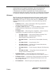
Managing the Switch Using SNMP Managing the Switch Using the Simple Network Management Protocol (SNMP) Note: Before you use SNMP you must connect the Switch’s Ethernet interface to an Ethernet network and configure its IP network address, its IP subnetwork mask, and its IP gateway address. Refer to the Ethernet Cabling and Configuring the Switch Ethernet Port paragraphs in this section. Network management is the process of planning, organizing, and controlling a communications-oriented system.
Managing the Switch Using SNMP Figure 3-13 illustrates the four main components involved in network management. Node Node SNMP Agent SNMP Agent Management Station SNMP Manager MIB Software Figure 3-13. Network Management Framework The Network Management Station A network management station is a centralized node (usually a dedicated workstation) connected to a network that runs some kind of network management software application (manager).
Managing the Switch Using SNMP symbols to alert the administrator to problems. Statistics Displays Agents provide statistics about the overall behavior of network components and the station manager displays the information in either numeric or graphical formats. The Node Agents The Switch has a built-in SNMP-compliant node agent. A management or node agent is a specific software component that resides on a network node (such as switches, routers, and servers).
Managing the Switch Using SNMP object identifier, or NULL. NULLs act as place holders reserved for future use. Access This property indicates the level of access to this particular object. Legal values are: read-only, read-write, write-only, and not accessible.
Managing the Switch Using SNMP specific. The Ancor MKII Accounting MIB is an enterprise MIB. The Simple Network Management Protocol SNMP is a well-defined, public standard that is widely used by the Internet community. The SNMP was first developed to address router management issues on the Internet and was designed to be protocol-independent (so it can be used over IP, IPX, AppleTalk, OSI, and other transport protocols as necessary).
Managing the Switch Using SNMP Switch How Much Traffic? SNMP Agent 12.5% at 4:15 PM Mgmt Station Figure 3-14 Polling-Only Data Collection Interrupt-Based Data Collection This method provides immediate notification to the network management station if an extraordinary event occurs (assuming the node has not crashed and the communication path between the node and the management station remains intact). A drawback of this method involves the resources required to generate the error (or trap).
Managing the Switch Using SNMP or graphical representation allowing the administrator to easily diagnose and manage the nodes and network traffic. Additionally, agents in the managed nodes can report error conditions (such as when user-set threshold levels have been exceeded) to the network management station without waiting to be polled for the information. Using the combined approach, when a managed node agent generates a trap, the network management station can query the node for additional information.
Managing the Switch Using SNMP Trap Community This name needs to accompany trap messages. If it does not match the name setting on the network management station that receives the traps, the trap messages are rejected and lost. By default, the trap community is set to “public.” Operation Types The administrator uses several basic SNMP operations to obtain information from managed node agents as well as edit the variables in MIB objects.
Managing the Switch Using SNMP Management Information Base (MIB) Switch MIB objects consist of 8 functional groups. These groups are: • system — MIB II Systems Group • interface — MIB II Interfaces Group • snmp — MIB II SNMP Group • fcFeConfig — Configuration • fcFeOp — Operation • fcFeError — Error • anMkiiAccounting — Accounting • fcFeCap — Capabilities • anMKiiUtility — MKII Utility MIB Each group has one or more tables associated with it.
Managing the Switch Using SNMP switch element • fcFeModuleTable — Module Table — a table of information about each module in the switch element • fcFPortConfigTable — Port Configuration Table — a table of the current configuration parameters for each port in the switch element Operation Group Tables • fcFPortOperTable — F_Port Operations Table — a table of the operational values of each port in the switch element • fcFPortFlogiTable — F_Port Login Table — a table of the service parameters defined dur
Managing the Switch Using SNMP usually identical to the host name, for example, “switch001”. The default value for this parameter is the empty string, “”. snmpContact The value of the SNMP Systems Group SysContact variable. This is usually set to identify the person or organization responsible for maintaining the host, for example, “Joe Cable, x1234”. The default value for this parameter is the empty string, “”. snmpLocation The value of the SNMP Systems Group SysName variable.
Section 4 Diagnostics/Troubleshooting Introduction Section 4 contains information to help you find problems. Power Supply Troubleshooting helps you solve AC power and Power Supply problems. Power-On-Self-Test (POST) checks the condition of Switch with the exception of the GBICs. Continuous Test checks the condition of the Switch including the GBICs and requires that you place a Loopback plug on each GBIC. Fiber Continuity tests for open fibers in the cable network.
Power Supply/Fan Troubleshooting Over Temperature LED (Red) Power Good LED (Grn) Fan Power Button Depressed (IN) Over Temperature LED (Red) System Status Power Supply Fail LED (Red) Lights on Back of Power Supply Logic Power Good LED (Grn) Front Panel Lights Corrective Action Standby Off NA* Off Off Off On No Press the Power Button (IN). ON - OK On Off On Off On Yes None AC source disruption Off Off Off Off Off NA Check AC source, Plug, and fuses.
Power Supply Troubleshooting System Status Power Good LED (Grn) Over Temperature LED (Red) Fan Power Good LED (Grn) Over Temperature LED (Red) Fan Power Button Depressed (IN) Lights on Back of Power Supply Over Temperature LED (Red) Lights on Back of Power Supply Power Supply Fail LED (Red) Good Supply(s) Logic Power Good LED (Grn) Front Panel Lights Bad Supply Corrective Action Standby Off Off Off Off Off On Off Off On No Press the Power Button (IN).
Power Supply Troubleshooting For example: 4-4 1. Note in Table 4-1 that when there is an AC Source disruption (System Status column) that the fan is OFF and the Power Good and Over Temperature LEDs are OFF. The state of the Power Button is not applicable. The Corrective Action indicates that you should check the AC source, the plug, and the fuses. 2.
Power-On-Self-Test (POST) Power-On-Self-Test (POST) Overview The Switch checks the state of the Mode switches as part of its power-up procedure. Refer to Figure 4-1 for the location of the Mode switches. Refer to the Chassis Switch Panel appendix for a description of these switches.
Power-On-Self-Test (POST) For example: • A PROM checksum failure is an example of a fatal error. This indicates that the PROM firmware is corrupt and the Switch may not run. • A failure associated with a Fibre Channel port is an example of a non-fatal error. The Switch can isolate the bad port and operate with the remaining ports. Note: Whether the problem is fatal or non-fatal, please contact Ancor Customer Service.
Power-On-Self-Test (POST) The POST diagnostic program performs the following basic tests: • checksum tests on the Boot firmware located in a PROM and the main Switch firmware located in FLASH memory • functional hardware tests on internal Switch memory • various read/write register and loopback data-path tests on the Switch logic • Frame Bus and Auto Route logic tests • Auto-Connect and Class 1 Connect logic tests • Switch Management port logic • Arbitrated Loop tests Heartbeat LED Blink Patte
Power-On-Self-Test (POST) PROM Checksum Failure (1 Blink) The Switch is not operable. This is a checksum test of the PROM designed to verify the integrity of the PROM data. A failure indicates the PROM data is corrupted and blinks the Heartbeat LED once between three-second pauses. No port Logged-in LEDs blink. RAM Failure (2 Blinks) The Switch is not operable. This is a test designed to verify the data and address busses to the SRAM as well as the SRAM integrity.
Power-On-Self-Test (POST) functions that can be performed within the confines of an individual ASIC. A failure indicates a faulty Switch ASIC and blinks the Heartbeat LED six times between three-second pauses. The Switch disables the ports associated with the bad ASIC and blinks their Logged-in LEDs. An ASIC that fails this test could affect the operation of the remaining ports. GBIC Bypass Port Loopback Test Failure (7 Blinks) The Switch is operable.
Power-On-Self-Test (POST) Switch Auto-Route Test Failure (10 Blinks) The Switch is operable. The Switch Auto-Route Test verifies the auto-route capability of individual ports to automatically route frames to the other ports in the chassis. A failure indicates an inability to successfully route frames between a port pair and blinks the Heartbeat LED ten times between three-second pauses. The Switch disables the failing ports or port-pairs and blinks their Logged-in LEDs.
Power-On-Self-Test (POST) Switch Management Port Failure (14 Blinks) The Switch is operable. The Switch Management Port test verifies the integrity of the Ethernet data bus functionality. A failure indicates that communication over the Ethernet port will most likely be adversely affected when this failure is indicated. The Heartbeat LED will blink fourteen times between three-second pauses. No port Logged-in LEDs blink. The remainder of the Switch and all ports have passed the tests and are operable.
Continuous Test Continuous Test Overview The Continuous Test button (when set to the TST position) causes the Switch to go from normal operate mode to continuous test mode. Refer to Figure 3-2. WORKS™ MKII COMMUNICATIONS, INC.
Continuous Test For example: • If the only problem with the Switch is one or more bad GBICs, the POST tests will not detect the problem at power-up because they do not test the GBICs. The Continuous Tests, however, will detect the problem and blink a heartbeat error code of eight (8) blinks to indicate a GBIC test failure. In this case, when you return the Continuous Test button to the IN position the Switch will read its error log and blink the Logged-in LED for the failing GBICs.
Continuous Test b. c. If the Heartbeat LED is blinking an error code of eight (8), there is a problem with one or more GBICs. 1. Press the Continuous Test button to place the Switch back in its normal operative (OP) mode. The Switch will read its error log, find one or more bad GBICs, and blink the appropriate port Logged-in LEDs. 2. You may have the ability to temporarily work around a bad GBIC if you don’t need all 16 ports.
Fiber Continuity Test Fiber Continuity Tests When there is a problem communicating over a particular fiber link and both the Switch and the N_Port adapter pass their respective tests, check the continuity of the fiber optic cables. Step 1 If possible, swap another set of fiber optic cables into the faulty link. Did this correct the problem? Yes Replace the faulty cable. No Contact your service representative.
4-16 Diagnostics/Troubleshooting GigWorks MkII-16 Switch Model MKII-BASE16 59003-01 Rev.
Section 5 Removal/Replacement Procedures Introduction The only Field Replaceable Units (FRUs) in the Switch are Input Fuses, GBICs, and the Power Supply(s). Input Fuse Removal 1. Unplug the AC Power Cable from the back of the Switch chassis. 2. Insert a thin-blade screwdriver into the slot behind the tab and use it to pull the Fuse Holder out the front of the AC Power Plug Assembly. 3. Pull the Fuse(s) from the Fuse Holder.
Input Fuse Replacement 1. Insert the Fuse(s) into the Fuse Holder. Refer to the Reference Information appendix for fuse-type information. 2. Insert the Fuse Holder into the right side of the AC Power Plug Assembly and press it in until it clicks in flush with the front surface of the assembly. 3. Plug the AC Power Cable into the AC Power Plug Assembly. Fuses (2) 4 Amp, 250V Fuse Holder 5-2 Removal/Replacement Procedures GigWorks MKII-16 Switch Model MKII-BASE16 59003-01 Rev.
GBIC GBIC GBICs may be removed and replaced with the power on and the Switch operating without disrupting traffic on other ports. Removal 1. Disconnect the cable (if one is connected) from the GBIC you are removing. 2a. Removing GBICs that have individually operated latches. See Step 2b for GBICs with bails. The typical GBIC is represented in the drawing below. You must press both latches in order to remove the GBIC.
GBIC 2b. Removing GBICs that have bail-operated latches. Some GBICs have latches that are operated by a built-in bail as represented in the drawing below. You simply use your finger-tip to rotate the bail up. Then pull on the bail to remove the GBIC. GBIC Connector GBIC Keyway (One on each side of the GBIC) Bail (Lift Bail to unlatch GBIC. Pull on Bail to remove GBIC) 5-4 Removal/Replacement Procedures GBIC Latch (One on each side of the GBIC) GigWorks MKII-16 Switch Model MKII-BASE16 59003-01 Rev.
GBIC Replacement GBICs may be removed and replaced with the power on and the Switch operating without disrupting traffic on other ports. 1. Orient the GBIC as shown in the drawing below. The Keyway is ON THE BOTTOM (as shown) for the top row of ports and ON THE TOP for the bottom row of ports. 2. Slide the GBIC into the port opening (the spring-loaded door will open as you push the GBIC in). If you can only slide the GBIC in about an inch (2.
Power Supply Power Supply Danger: Do not attempt to open the covers of the power supply. Power supplies are not serviceable and must be replaced as a unit. Danger: L’alimentation électrique ne se répare pas. En cas de panne, la remplacer au complet. Ne pas essayer d’en ouvrir le boîtier. Gefahr: Versuchen Sie auf keinen Fall, die Abdeckung des Netzteils zu entfernen. Die Netzteile sind nicht wartbar. Sie müssen als ganze Einheit ersetzt werden.
Power Supply Replacement If the Switch contains two Power Supplies, either supply is “Hot-Pluggable”. That is, one supply can be replaced while the Switch is powered-up and operating as long as the other supply is operating properly. 1. If you are placing a Power Supply in a Power Supply Bay that currently has a Cover Plate on it, first remove the Cover Plate. Use a large flat-blade screwdriver to turn each of the two Locking-Screws 1/4 turn counterclockwise.
5-8 Removal/Replacement Procedures GigWorks MKII-16 Switch Model MKII-BASE16 59003-01 Rev.
Appendix A Reference Information Appendix A contains the specifications for the GigWorks MKII-16 Switch Model MKII-BASE16. Refer to the Switch Overview in Section 1 for the location of all connections, switches, and components. Ancor Customer Service Phone: ........................................ (612) 932-4040 Fax: ............................................ (612) 932-4037 Attn: Customer Service E mail: ....................................... support@ancor.com Web: ..............................
Reference Information A-2 FL_Port Characteristics: .............. Each FL_Port can support 1-126 NL_Ports Each public loop can handle both public and private loop transactions Number of Fibre Channel Ports: 16 Ports per chassis; Populated by 2 to 16 GBICs in one GBIC increments. Scalability: ................................. Up to 192 fabric ports in a multi-stage non-cascaded topology. Multi-stage topology uses cross-connecting for the fewest fabric hops. Multi-stage Fabric Hops: .............
Reference Information Maximum Frame Sizes: ............. System Processor: ...................... Gb/s, even though backplanes supply up to 32 Gb/s. Model MKII-BASE16 — 2148 bytes (2112byte payload) for all classes of service supported by the Switch. Model MKII-STD16 — Class 1: 2148 bytes (2112 byte payload) Class 2 or Class 3: 548 bytes (512 byte payload) Superscalar 40-MHz Intel i960HA Switch Maintainability Maintenance Strategy: ...............
Reference Information Switch Agent : ........................... TFTP: ......................................... Allows a network management station to obtain configuration values, traffic information, and failure data pertaining to the Fibre Channels via SNMP through the Ethernet interface.
Reference Information Switch Environmental Operational Temperature: ............ 10 to 40°C (50 to 104°F) Operating Humidity: ................... 25 to 80%, non-condensing Operating Altitude: .................... 0 to 3048m (0 to 10,000 feet) Operating Vibration: .................. During/after (in any axis) of magnitude: 2.54mm (0.1”) from 5 to 14 Hz 0.1G from 14-300 Hz Operating Shock: ....................... During/after (in any axis) of magnitude: 1.0G for 15 m seconds Air flow: .............
Reference Information Shortwave Laser GBIC (multi-mode) Connector: ................................... Duplex SC Color coding: ............................... Beige or black exposed connector surfaces Cable:........................................... Fibre Channel 100-M5-SN-I or 100-M5-SL-I (50um multimode). Fibre Channel 100-M6-SN-I or 100-M6-SL-I (62.5um multimode) Wavelength: ................................. 770 - 860 nm Open Fiber Control:.....................
Reference Information Copper Inter-Enclosure GBIC (active) Connector: ................................... Style 1 (9 pin D-subminiature, DB-9) Style 2 (HSSDC, looks like wide phone jack or RJ45) Fibre Channel 100-TW-EL-S (shielded dual parallel pair cable) Fibre Channel 100-TP-EL-S (shielded dual twisted pair cable) Differential Impedance: ............... 150 ohms +/- 10 ohms Transmitted Signal:...................... 1100 - 2000 mV differential PECL Received Signal: ..........................
Reference Information 480.16 (18.904") 475.437 (18.718") 2.362 (.093") 8x10.312 (.406") 2 4 6 8 14 16 10 12 OP TST 1 3 5 9 11 13 15 16.560 (.652") 2.39 (.094") 8x7.92 (.312") 12.319 (.485") 60.325 (2.375") 72.64 (2.86") 85.34 (3.36") 7 Front View Dimensions in mm (inches) Cover Plate (if no second Power Supply) 91.694 (3.610") 447.04 (17.
Reference Information 562.940 (22.163”) 20.701 (.815”) Allow 165mm (6.5”) clearance for airflow 482.6 (19.0”) 542.239 (21.348”) Dimensions in mm (inches) 447.04 (17.6”) Allow 165mm (6.5”) clearance for airflow Figure A-2 GigWorks MKII-16 Switch Model MKII-BASE16 Dimensions (Top View) GigWorks MKII-16 Switch Model MKII-BASE16 Installer's/User's Manual 59003-01 Rev.
A-10 Reference Information GigWorks MKII-16 Switch Model MKII-BASE16 59003-01 Rev.
Appendix B Ancor Customer Service Appendix B contains information about Ancor Customer Service. Ancor Customer Service Ancor offers several service programs including Basic Warranty service: Help Desk Description: Consists of: • Assistance related to questions about Ancor products. • Diagnostic assistance. • Providing information about available fixes and workarounds.
Ancor Customer Service Software Support Ancor actively supports the current software/firmware release and the prior release for 6 months following the general availability date for the current release. You are encouraged to keep your software/firmware levels current. For supported software: • Ancor will attempt to isolate and verify the reported problem. • If applicable, Ancor will give you a software/firmware fix or workaround along with descriptive documentation.
Appendix C Chassis Switch Panel Chassis Switch Panel Refer to Figure C-1 for the location of the Chassis Switch Panel. The Chassis Switch panel contains a microprocessor Reset button, switches for bypassing the Flash memory and Watchdog Timer, Test Mode select switches, and switches for configuring a multi-stage Switch fabric. Descriptions of these switches and buttons follows.
Chassis Switch Panel Reset Refer to Figure C-2. RESET Figure C-2 Reset Button Use the Reset button only under the direction of your service representative. Force PROM Mode There may be circumstances when the control firmware, located in Flash memory, could be made incompatible with Switch operation (for example, through a failed Flash load operation) and yet the Flash Check Sum could be correct.
Chassis Switch Panel Watch Dog Timer Disable Refer to Figure C-3. The Switch contains a Watchdog timer that resets the internal processor in the event of a hangup. The Watchdog Disable switch, when ON, disables the Watchdog timer. The Watchdog Disable switch must be in the OFF position for normal Switch operation. Use the Watchdog Timer Disable switch only under the direction of your service representative. Test Mode Refer to Figure C-4. The switches are shown in the 00 position.
Chassis Switch Panel Chassis #, Fabric #, Stage #, and Area # Configuration Switches The Chassis #, Fabric #, Stage #, and Area # configuration switches (shown in Figure C-5) are not used. AREA 543210 FABRIC STAGE 3 210 10 1 1 1 0 0 0 1 0 543210 CHASSIS Figure C-5 Chassis #, Fabric ID, Stage #, and Area # Configuration Switches C-4 Chassis Switch Panel GigWorks MKII-16 Switch Model MKII-BASE16 59003-01 Rev.