
user manual


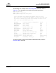


Table Of Contents
- Table of Contents
- Section 1 Introduction
- Section 2 Command Line Interface Usage
- Section 3 User Account Configuration
- Section 4 Network and Fabric Configuration
- Section 5 Switch Configuration
- 5.1 Displaying Switch Information
- 5.2 Managing Switch Services
- 5.3 Managing Switch Configurations
- 5.4 Paging a Switch
- 5.5 Setting the Date and Time
- 5.6 Resetting a Switch
- 5.7 Installing Firmware
- 5.8 Managing Switch Feature Upgrades
- Section 6 Port Configuration
- Section 7 Zoning Configuration
- Section 8 Connection Security Configuration
- Section 9 Device Security Configuration
- Section 10 RADIUS Server Configuration
- Section 11 Event Log Configuration
- Section 12 Simple Network Management Protocol Configuration
- Section 13 Command Reference
- 13.1 Access Authority
- 13.2 Syntax and Keywords
- 13.3 Notes and Examples
- 13.4 Command Listing
- Admin
- Alias
- Config
- Create
- Date
- Exit
- Fcping
- Fctrace
- Feature
- Firmware Install
- Group
- Hardreset
- Help
- History
- Hotreset
- Image
- Lip
- Logout
- Passwd
- Ping
- Ps
- Quit
- Reset
- Security
- Securityset
- Set Alarm
- Set Beacon
- Set Config Port
- Set Config Security
- Set Config Security Portbinding
- Set Config Switch
- Set Config Threshold
- Set Config Zoning
- Set Log
- Set Pagebreak
- Set Port
- Set Setup Radius
- Set Setup Services
- Set Setup SNMP
- Set Setup System
- Set Switch State
- Set Timezone
- Show About
- Show Alarm
- Show Broadcast
- Show Chassis
- Show Config Port
- Show Config Security
- Show Config Security Portbinding
- Show Config Switch
- Show Config Threshold
- Show Config Zoning
- Show Domains
- Show Donor
- Show Fabric
- Show FDMI
- Show Interface
- Show Log
- Show LSDB
- Show Media
- Show Mem
- Show NS
- Show Pagebreak
- Show Perf
- Show Port
- Show Post Log
- Show Setup Mfg
- Show Setup Radius
- Show Setup Services
- Show Setup SNMP
- Show Setup System
- Show Steering
- Show Switch
- Show Timezone
- Show Topology
- Show Users
- Show Version
- Shutdown
- Test Cancel
- Test Port
- Test Status
- Uptime
- User
- Whoami
- Zone
- Zoneset
- Zoning
- Index

5 – Switch Configuration
Displaying Switch Information
59183-01 A 5-7
A
5.1.5
Hardware Information
Enter the Show Chassis command to display the status of the switch hardware
including fans, power supplies, internal temperature, and Heartbeat LED status.
The following is an example of the Show Chassis command for model 5602:
SANbox #> show chassis
Chassis Information
-------------------
BoardTemp (1) - Degrees Celsius 36
FanStatus (1) Good
FanStatus (2) Good
FanDirection (1) BackToFront
FanDirection (2) BackToFront
PowerSupplyStatus (1) Good
PowerSupplyStatus (2) Good
HeartBeatCode 1
HeartBeatStatus Normal
The HeartBeatCode and HeartBeatStatus entries indicate the Power-on Self Test
(POST) results revealed by the Heartbeat LED blink patterns. The result is normal
operation or a blink pattern indicating a critical error as described in Table 5-1.
Refer to your Installation Guide for more information about the Heartbeat LED and
its blink patterns.
Table 5-1. Heartbeat LED Activity
HeartBeatCode–HeartBeatStatus Description
1–Normal One blink per second–Normal operation
2–AppDied Two blink cluster–Internal firmware failure
3–PostFailed Three blink cluster–Fatal POST error
4–CorruptFilesystem Four blink cluster–Configuration file system error
5–Overheating Five blink cluster– Over temperature