Hardware Installation Guide for the QLA12160 Board 64-Bit PCI Dual SCSI Host Adapter Board for the PCI Bus DC8151101-00 C September 14, 2001
QLogic Corporation Information furnished in this manual is believed to be accurate and reliable. However, QLogic Corporation assumes no responsibility for its use, nor for any infringements of patents or other rights of third parties which may result from its use. QLogic Corporation reserves the right to change product specifications at any time without notice. Applications described in this document for any of these products are for illustrative purposes only.
Table of Contents Section 1 1.1 1.2 1.2.1 Introduction Product Description . . . . . . . . . . . . . . . . . . . . . . . . . . . . . . . . Features . . . . . . . . . . . . . . . . . . . . . . . . . . . . . . . . . . . . . . . . Mixed Peripheral Support . . . . . . . . . . . . . . . . . . . . . . . . Section 2 2.1 2.2 2.3 2.4 2.5 2.6 2.7 Hardware Installation Preinstallation Procedures. . . . . . . . . . . . . . . . . . . . . . . . . . . What You Need for Installation . . . . . . . . . . . . . . . . . . .
Table of Contents Appendix B B.1 B.2 QLA12160 Hardware Installation Guide SCSI Termination Setting the SCSI Termination . . . . . . . . . . . . . . . . . . . . . . . Termination (Jumpers) for the QLA12160 . . . . . . . . . . . . . . Appendix C B-1 B-1 Specifications FIGURES Figure 2-1 B-1 Page QLA12160 Board Layout. . . . . . . . . . . . . . . . . . . . . . . . . . . . . . . QLA12160 Jumper Termination . . . . . . . . . . . . . . . . . . . . . . . . .
Section 1 Introduction NOTE: This installation guide applies to the following QLogic host adapter boards, collectively referred to as the QLA12160 board unless otherwise noted: ■ ■ QLA12160/33 (DC8110402-06) QLA12160/66 (DC8110402-07) The QLA12160 board (wide, low voltage differential [LVD]), dual port, Ultra3, 64-bit PCI) contains the ISP12160A/33 or ISP12160A/66 chip. 1.
Features 1 – Introduction The QLA12160 board supports Ultra, Ultra2, and Ultra3 transfer speeds. The board can connect computers to other computers or to peripheral devices such as CD-ROM drives, tape drives, and hard disk drives.
1 – Introduction Features ■ Support for LVD mode ■ Support for up to 30 LVD SCSI devices (15 per channel) ■ Support for logical unit numbers (LUNs) 0–15 ■ Support for bus master DMA ■ Fast!UTIL BIOS utility to customize the configuration parameters on the QLA12160 board and attached drives ■ Active termination ■ Active negation 1.2.
Features 1-4 1 – Introduction DC8151101-00 C
Section 2 Hardware Installation 2.1 Preinstallation Procedures Before installing your QLA12160 board, take the time to read this instruction guide. CAUTION! ■ Your computer, the QLA12160 board, and each SCSI device must be configured properly for optimum performance. Refer to the appropriate documentation to configure your computer and SCSI devices. ■ Pay particular attention to the SCSI ID assignment. The QLA12160 board is set at the factory for SCSI ID 7.
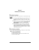
Setting the SCSI Termination 2 – Hardware Installation Figure 2-1 identifies the QLA12160 board components referenced throughout this section. DC8110402 J9 SCSI LED J5 J6 J7J8 J1 4 1 J3 3 3 3 3 ISP CHIP J2 Figure 2-1. QLA12160 Board Layout 2.3 Setting the SCSI Termination Termination for the QLA12160 board is set automatically in most cases. You can change the termination using the Fast!UTIL software (see section A.2.3).
2 – Hardware Installation Installation in the Computer light to the J9 jumper block on the QLA12160 board (pins 1 and 4 are positive). If your boot drive is an integrated device electronics (IDE) drive or connected to a different adapter, you can connect an LED to the QLA12160 board jumper blocks to show activity of devices connected to your QLA12160 board. 2.6 Installation in the Computer If you changed the termination on the QLA12160 board, double-check the new setting prior to installation.
Installation in the Computer 2 – Hardware Installation 5. Unscrew and remove the slot cover. Retain the screw to use when you install the QLA12160 board. 6. Place the QLA12160 board into the slot. Carefully press the board into the slot until it seats firmly. NOTE: QLA12160 boards are designed with the components on the opposite side compared with non-PCI boards. 7. Secure the QLA12160 board with the slot cover screw. 8. Install the cable.
2 – Hardware Installation Installation Help See the Software Installation Guide for the QLA12160 Board on the QLogic web site http://www.qlogic.com/ for detailed instructions on how to install the QLA12160 board’s software drivers. If the information displayed on your monitor is not correct and you have checked the QLA12160 board’s configuration, see section 3 for troubleshooting information. 2.
Installation Help 2-6 2 – Hardware Installation BC8151101-00 C
Section 3 Troubleshooting 3.1 Problems After Installation There are three types of installation problems that can cause your QLA12160 board to function incorrectly: hardware problems, system configuration problems, and SCSI problems. This section provides itemized checklists to help you determine why your QLA12160 board is functioning incorrectly. NOTE: The latest versions of release notes, software drivers, flash BIOS, and documentation are available on the QLogic web site, http://www.qlogic.com/. 3.
SCSI Problem Checklist 3 – Troubleshooting 3.4 SCSI Problem Checklist ■ Is the SCSI bus termination for the QLA12160 board set correctly (see appendixes A and B)? ■ Is the termination for all devices on the SCSI bus set correctly? ■ Were all SCSI devices powered up before you powered up the PC? ■ Does each device have a unique SCSI ID? Each device must have a unique ID between 0 and 15. The QLA12160 board is set to SCSI ID 7 at the factory.
Appendix A Fast!UTIL A.1 Introduction This appendix provides detailed configuration information for advanced users who want to customize the configuration of the QLA12160 board and the connected devices. The QLA12160 board is configured at the factory to provide maximum performance. When your board is operating at maximum performance, it may not be 100% compatible with some older SCSI-1 devices. If you are using a SCSI-1 device, see section A.5 for more information.
Configuration Settings A – Fast!UTIL A.2.1 Host Adapter Settings From the Configuration Settings menu in Fast!UTIL, select Host Adapter Settings. Default settings for the QLA12160 host adapter board are listed in table A-1 and described in the following paragraphs. Table A-1.
A – Fast!UTIL ❑ Configuration Settings Safe. All optimal configuration settings are disabled and all attached devices work in minimal configuration (narrow, asynchronous mode). NOTE: Safe mode is primarily for troubleshooting SCSI devices that are not functioning properly during normal system operation. ■ Drivers Load RISC Code. When this setting is Enabled, the QLA12160 board uses the RISC firmware that is embedded in the software driver.
Configuration Settings A – Fast!UTIL Table A-2.
A – Fast!UTIL Configuration Settings ■ Negotiate Synchronous. When set to Yes, the QLA12160 board negotiates synchronous data transfers with the device. When set to No, the QLA12160 board uses only asynchronous data transfers. The default is Yes. ■ Tagged Queuing. When set to Yes, the device queues multiple commands. When set to No, multiple queues are not supported. The default is Yes. ■ Sync Offset.
Configuration Settings ■ A – Fast!UTIL SCSI termination Termination for the QLA12160 board can be set in one of three ways: ❑ ❑ ❑ Automatic (default) Manual (through Fast!UTIL) Jumpers NOTE: The last SCSI device on each end of the SCSI bus must be terminated. The QLA12160 board is a dual-port host adapter. Each port is a separate SCSI bus and must be terminated independently. The port one and two connectors are listed in table A-4. Table A-4.
A – Fast!UTIL Configuration Settings connected to the other connector. Use this setting for the QLA12160 board’s port two (J2) when the port two connector is not at one end of the SCSI bus and you have narrow devices at one end of the bus and wide devices at the other end. A.2.4 Autoconfigure SCSI Devices NOTE: You must set the Adapter Configuration setting in Host Adapter Settings to Manual (see section A.2.
Scan SCSI Bus A – Fast!UTIL A.2.6 Restore Default Settings The Restore Defaults option from the Configuration Settings menu restores the QLA12160 board default settings, which are displayed in SCSI Device Settings. Use the arrow keys to change settings. See section A.2.2 for more information about SCSI Device Settings and see section A.2.1 for Host Adapter Settings. A.2.7 Raw NVRAM Data This option displays the adapter’s nonvolatile random access memory (NVRAM) contents in hexadecimal format.
A – Fast!UTIL Using SCSI-1 Devices 3. Select SCSI Device Settings. A window displays the settings for each SCSI device. Make the following changes for each SCSI ID to which a SCSI-1 device is assigned. a. b. c. d. Change the Negotiate Wide setting to No. Save the parameters. Exit Fast!UTIL. Reboot the system. 4. If your SCSI device still does not function correctly, repeat steps 1 through 3.
Using SCSI-1 Devices A-10 A – Fast!UTIL DC8151101-00 C
Appendix B SCSI Termination B.1 Setting the SCSI Termination The first and last physical SCSI devices on each end of the SCSI bus must be terminated. Termination is set automatically through Fast!UTIL (see section A.2.1). The QLA12160 board offers the additional option of terminating with jumpers (see section B.2). Some cables have multiple connectors for connecting several devices to one of the board’s connectors.
Termination (Jumpers) for the QLA12160 B – SCSI Termination The QLA12160 board jumper block is illustrated in figure B-1. . DC8110402 J9 SCSI LED J5J6 J7J8 4 1 3 3 3 3 ISP CHIP QLA12160 (DC8110402) Figure B-1. QLA12160 Jumper Termination The following paragraphs give manual termination instructions. B-2 ■ Termination disabled. Removing the jumpers from J5 and J6 disables termination for port one.
Appendix C Specifications Table C-1. QLA12160 Board Operating Environment Environment Operating temperature Storage temperature Minimum Maximum 0°C (32°F) 55°C (131°F) –20°C (–4°F) 70°C (158°F) Relative humidity (noncondensing) 10% 90% Storage humidity (noncondensing) 5% 95% Table C-2. QLA12160 Board Specifications Type Specification Host bus Conforms to PCI Local Bus Rev. 2.2 specification SCSI standard ANSI X3.
C – Specifications Table C-2. QLA12160 Board Specifications (Continued) Type Specification Connectors 68-pin, high-density, internal SCSI-2 connector (port one) Two 68-pin, external VHDCs Form factor 17.78cm × 10.67cm (7.0" × 4.