Liquid Cooled Millermatic Compatible™ Owner’s Manual Product: Python Manual: 091-0597 Serial: 07030001 Voltage Rating: 24 VDC Revision: March 2007 Gun Models: 248-8xx 400 Ampere Push-Pull Welding Gun
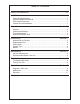
Table of Contents Safety Considerations.........................................................................i-iii Installation................................................................................ Section A Technical Specifications......................................................................................1 Support Equipment Required..............................................................................1 Gun Lead Connections.....................................................
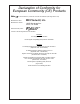
Declaration of Conformity for European Community (CE) Products Note This information is provided for units with CE certification (see rating label on unit). MK MillerProducts, Electric Mfg.Inc. Co. Manufacturer’s Name: 1635 W.Armstrong Spencer Street 16882 Ave.
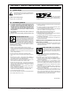
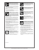
SECTION 1 – SAfETY PRECAUTIONS - READ BEfORE USING som _nd_7/02 1-1. Symbol Usage Means Warning! Watch Out! There are possible hazards with this procedure! The possible hazards are shown in the adjoining symbols. � Marks a special safety message. � Means “Note”; not safety related. This group of symbols means Warning! Watch Out! possible ELECTRIC SHOCK, MOVING PARTS, and HOT PARTS hazards. Consult symbols and related instructions below for necessary actions to avoid the hazards. 1-2.
ARC RAYS can burn eyes and skin. Arc rays from the welding process produce intense visible and invisible (ultraviolet and infrared) rays that can burn eyes and skin. Sparks fly off from the weld. � Wear a welding helmet fitted with a proper shade of filter to protect your face and eyes when welding or watching (see ANSI Z49.1 and Z87.1 listed in Safety Standards). � Wear approved safety glasses with side shields under your helmet.
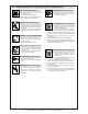
1-3. Additional Symbols for Installation, Operation, And Maintenance fIRE OR EXPLOSION hazard. MOVING PARTS can cause injury. � Do not install or place unit on, over, or near combustible surfaces. � Do not install unit near flammables. � Do not overload building wiring – be sure power supply system is properly sized, rated, and protected to handle this unit. � Keep away from moving parts such as fans. � Keep all doors, panels, covers, and guards closed and securely in place.
1-4. Principal Safety Standards Safety in Welding, Cutting, and Allied Processes, ANSI Standard Z49.1, from American Welding Society, 550 N.W. LeJeune Rd, Miami FL 33126 (phone: 305-443-9353, website: www.aws.org). Boulevard, Rexdale, Ontario, Canada M9W 1R3 (phone: 800–463–6727 or in Toronto 416–747–4044, website: www.csa–international.org). Recommended Safe Practices for the Preparation for Welding and Cutting of Containers and Piping, American Welding Society Standard AWS F4.
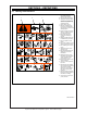
SECTION 2 – DEfINITIONS 2-1. Warning Label Definitions A B 1 1.1 2 2.1 3 3.1 4 4.1 5 + C 1.2 2.2 1.3 2.3 3.2 + 3.3 + + 6 S-178 936 A. Warning! Watch Out! There are possible hazards as shown by the symbols. B. Drive rolls can injure fingers. C. Welding wire and drive parts are at welding voltage during operation – keep hands and metal objects clear. 1 Electric shock can kill. 1.1 Wear dry insulating gloves. Do not touch electrode with bare hand. Do not wear wet or damaged gloves. 1.
2-3. Symbols And Definitions Note Some symbols are found only on CE products.
Thank You For selecting a quality product. We want you to take pride in operating this product...as much pride as we have in bringing the product to you! Please Examine Carton and Equipment For Damage Immediately When this equipment is shipped, title passes to the purchaser upon receipt by the carrier. Consequently, claims for material damaged in shipment must be made by the purchaser against the transportation company at the time the shipment is received.
Section A Installation Technical Specifications Wire Capacity Aluminum or Cored Wire............................... .030" - 1/16" (0.8 mm - 1.6 mm) Solid and Hard Wire...................................... .030" - .045" (0.8 mm - 1.2 mm) Wire Speed (At rated feeder input voltage)..................... 800 ipm (20.3 mpm) Duty Cycle - 60% (All ratings are using Argon gas).........................400 Amps Shipping Weight (approximate)....................................... 19.29 lbs. (8.
Coolant Recommendations Use Cobra Coolant (Aluminum Protection), P/N 931-0060. Cobra Coolant does not contain reactive sulphur or chlorine and does not react with copper, brass or aluminum. The coolant flow rate should be a minimum of 15 GPH (1 qt/min) between 35 and 45psi. Contact the re-circulator manufacturer for specifications on pressure.
Optional insulated V-groove drive rolls are also available for aluminum wire if desired (see optional kits). Drive roll tension is accomplished with a unique spring-loaded pressure screw. The Millermatic Compatible™ Python ® comes from the factory with the pressure adjustment screw preset. NO ADJUSTMENT required for ANY WIRE SIZE OR ALLOY Drive Roll Installation/Removal Note: Neither of the handles needs to be removed to access the drive or idler rolls. 1. Pull the cam lever away from the idler roll.
Section C Options and Accessories Insulated Drive Roll Kits Used to prevent preheating of the wire which may soften it and clog the liner. This picking up of current at the drive rolls rather than at the contact tip is usually not a problem unless using too large of a contact tip or excessively oxidized aluminum wire. Insulated Groove Drive Roll Kit.......................................................005-0640 For .030" (0.8 mm) dia. aluminum wire. Includes insulated drive roll and idler roll assy.
Contact Tips Heavy Duty Contact Tip - 3/8" Diameter* Wire Size Tip ID .030” (0.8mm) .040” (1.0mm) .035” (0.9mm) Arc Tip Length .045” (1.1mm) Spray Short Spray 1.57” (39.9mm) 1.82” (46.2mm) 1.57” (39.9mm) .035" (0.9mm) .045" (1.1mm) .045" (1.1mm) .054" (1.37mm) 3/64” (1.2mm) .054” (1.37mm) Short Short Spray 1.82” (46.2mm) 1.82” (46.2mm) 1.57” (39.9mm) Part No. 621-0390-25 621-0396-25 621-0391-25 621-0391-250† 621-0391-500†† 621-0397-25 621-0398-25 621-0392-25 621-0392-250† 3/64” (1.2mm) .
Optional Barrels - Liquid Cooled 6" Straight........................................................................................... 003-2315 6" Curved, 45°.................................................................................... 003-2316 12" Straight ........................................................................................ 003-2318 12" Curved, 45° ................................................................................. 003-2319 18" Straight ...........................
Recommended Spare Parts Listed in the table below is the factory recommendation of the necessary spare parts which should be kept on hand for maintaining proper operation of the liquid cooled Millermatic Compatible™ Python® welding gun. This list, in no way, indicates that these parts are more likely to fail or cause equipment damage. This is not an indication of premature failure or defect in manufacture of said parts. Recommended Spare Parts List Qty.
Section E Troubleshooting Guide Disconnect Power Before Troubleshooting. To aid in troubleshooting problems with your welding equipment, it is best to understand the basic theory of operation for this Push-Pull System. The slave motor in the feeder runs at a fast, constant speed, but has very low torque. It is always trying to feed more wire than the gun motor wants, and when the motor gets all it wants, it slows the slave motor, preventing a bird’s nest.
Troubleshooting Table Symptoms No wire feed at gun, feeder not operating, i.e. no slave motor or brake solenoid. No wire feed at gun, feeder operating properly. Wire feeds, but welding wire is not energized. Wire feeds erratically. Wire feeds one speed only. Wire walks out of drive rolls. Cause Circuit breaker in feeder/ control box open. Remedy Reset. Micro-switch defective/not Replace switch. Check being activated. switch for operation. Broken electrical cable.
Section F Appendices Liquid Cooled Millermatic Compatible™ Python® Diagrams / Parts List Head Assembly Exploded Parts View........................................ 10 Head Assembly Parts List.......................................................... 11 Front Body Assembly Parts View............................................... 12 Rear Body Assembly Parts View............................................... 13 Barrel Assembly Parts View.......................................................
Apply compound Noalox to contact surfaces for installation.
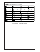
Liquid Cooled Millermatic Compatible™ Python® Owner's Manual - page 12 Qty. 1 1 1 1 1 1 1 1 1 1 2 1 2 No. 1 2 3 4 5 6 7 8 9 10 11 12 13 320-0084 319-0258 319-0254 211-0077 003-2287 005-0695 003-2209 003-2153 005-0701 003-2125 003-2108 005-0694 002-0629 Part No.
Liquid Cooled Millermatic Compatible™ Python® Front Body Assembly P/N 003-2108 Items 3, 4 & 9 available as package kit: P/N 005-0686 Liquid Cooled Millermatic Compatible™ Python® Front Body Assembly No. Qty. Part No. Description 1 - - 2 - - 3* 1 325-0206 10-24 x 3/8 PH Screw 4* 1 333-0082 # 10 Lock Washer 5 1 419-0092 0.29 x 0.047 x 0.32 Comp.
Liquid Cooled Millermatic Compatible™ Python® Rear Body Assembly P/N 003-2287 APPLY SILICONE LUBRICANT FOR INSTALLATION Liquid Cooled Millermatic Compatible™ Python® Rear Body Assembly No. Qty. Part No. Description 1 - - Not available separately 2 6 303-0096 O-Ring .145 ID x .
Liquid Cooled Millermatic Compatible™ Python® Barrel Assembly P/N 003-2317 *Apply silicone lubricant to items 5, and 6 before installing. Millermatic Compatible™ Python® Liquid Cooled 60º Barrel Assembly No. Qty. Part No. Description 1 - - Not available separately 2 1 003-2213 Assy Taper Lock Barrel 3 1 261-0141 Insulator Barrel 4 1 261-0381 Insulator Cup with five O-Rings 5* 8 303-0010 O-Ring .489 ID x .07 W 6* 2 303-0094 O-Ring .301 ID x .
CUP INSULATOR AND O-RING MAINTENANCE CAUTION: Power-off the coolant pump before disassembling liquid-cooled barrels. 1. Unscrew Retaining Nut and slide back on barrel. 2. Using a firm pull and twist action, the Liquid-Cooled Gas Cup can be removed from the Cup Insulator. 3. Inspect the Cup Insulator and o-rings (included with Insulator) for wear and proper lubrication. It is considered good practice to replace all o-rings at the same time. 4.
Liquid CooledMillermatic Compatible™ Python® Lead Assembly, P/N 003-2309 Series Liquid Cooled Millermatic Compatible™ Python® Lead Assembly No Qty Description 15' Part No. 25' Part No. 35' Part No. 50' Part No.
Liquid Cooled Millermatic Compatible™ Python® Power/Gas Connector 003-2322 Liquid Cooled Millermatic Compatible™ Python® Power/Gas Connector No. Qty. Part No. Description 1 1 003-2323 S/A Conn Power Gas WC 2 2 153-1210 Pin Power Assy 3 1 303-0102 O-Ring, 0.487 ID x .
Liquid Cooled Millermatic Compatible™ Python® Electrical Schematic/Connector Pinout Polarizing Key "X" Clocked Connector Viewed from back of connector WARNING • Do not touch live electrical parts. • Disconnect input power or stop engine before servicing. ELECTRIC SHOCK HAZARD • Do not operate with covers removed. • Have only qualified persons install, use, or service this units.
October 1, 2006 LIMITED WARRANTY Effective October 1, 2006 This warranty supersedes all previous MK Products warranties and is exclusive, with no other guarantees or warranties expressed or implied. LIMITED WARRANTY - MK Products Inc., Irvine, California warrants that all new and unused equipment furnished by MK Products is free from defects in workmanship and material as of the time and place of delivery by MK Products.
16882 Armstrong Ave. Irvine, CA 92606 Tel (949)863-1234 Fax (949)474-1428 www.mkproducts.