
User guide


Technical data T82
34
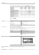
The following connection combinations are possible when both sensor inputs are assigned:
Sensor input 1
Sensor input 2
RTD or
resistance
transmitter, 2-
wire
RTD or
resistance
transmitter, 3-
wire
RTD or
resistance
transmitter, 4-
wire
Thermocouple
(TC), voltage
transmitter
RTD or resistance
transmitter, 2-wire
4 4 - 4
RTD or resistance
transmitter, 3-wire
4 4 - 4
RTD or resistance
transmitter, 4-wire
- - - -
Thermocouple (TC),
voltage transmitter
4 4 4 4
12.2 Output
Output signal
Analog output 4 to 20 mA, 20 to 4 mA (can be inverted)
Signal encoding FSK ±0.5 mA via current signal
Data transmission rate 1200 baud
Galvanic isolation U = 2 kV AC (input/output)
Failure information
Failure information as per NAMUR NE43:
Failure information is created if the measuring information is missing or not valid. A complete list
of all the errors occurring in the measuring system is created.
Underranging Linear drop from 4.0 to 3.8 mA
Overranging Linear increase from 20.0 to 20.5 mA
Failure, e.g. sensor breakage; sensor short circuit ≤ 3.6 mA ("low") or ≥ 21 mA ("high"), can be selected
The "high" alarm setting can be set between 21.6 mA and 23 mA,
thus providing the flexibility needed to meet the requirements of
various control systems.
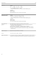
Load
R
b max.
= (U
b max.
- 11 V) / 0.023 A (current output)
Ub
42 V
1348
1098
250
11 V
0
36.25 V16.75 V
Supply voltage (V DC)
Load ( )Ω
A0014066-EN
Linearization/transmission
behavior
Temperature-linear, resistance-linear, voltage-linear
Mains voltage filter 50/60 Hz