
User guide


Wiring T82
14
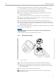
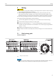
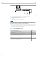
5.2 Connecting the sensor cables
Terminal assignment of the sensor terminals (® å 5, ä 13).
NOTICE
When connecting 2 sensors, ensure that there is no galvanic connection between the
sensors (e.g. caused by sensor elements that are not isolated from the thermowell). The
resulting equalizing currents distort the measurement considerably.
►
The sensors must remain galvanically isolated from one another by connecting each sensor
separately to a transmitter. The transmitter provides sufficient galvanic isolation (> 2 kV AC)
between the input and output.
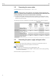
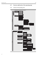
The following connection combinations are possible when both sensor inputs are assigned:
Sensor input 1
Sensor input 2
RTD or
resistance
transmitter,
two-wire
RTD or
resistance
transmitter,
three-wire
RTD or
resistance
transmitter,
four-wire
Thermocouple
(TC), voltage
transmitter
RTD or resistance
transmitter, two-wire
4 4 - 4
RTD or resistance
transmitter, three-wire
4 4 - 4
RTD or resistance
transmitter, four-wire
- - - -
Thermocouple (TC),
voltage transmitter
4 4 4 4
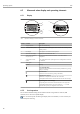
5.3 Connecting the power supply and signal cables
!
CAUTION
►
Switch off power supply before installing or connecting the head transmitter. Failure to
observe this may result in destruction of parts of the electronics.
Cable specification
• A normal device cable suffices if only the analog signal is used.
• A shielded cable is recommended for HART
®
communication. Take the plant grounding
concept into consideration.
Please also observe the general procedure on (® ä 13).