Operating Instructions T82 Dual-Input Temperature Head Transmitter BA01139O/09/EN/13.10 71207043 Valid as of version 01.
T82 Brief overview For quick and straightforward commissioning: Safety instructions (® ä 6) t Installation instructions (® ä 8) t Wiring (® ä 13) t Display and operating elements (® ä 17) t Commissioning Commissioning using the interface - quick start for device configuration for standard operation Customer-specific configuration Complex measurement tasks require additional functions to be configured that the user can individually select, set and adapt to his process conditions by setting the app
Table of contents T82 Table of contents 1 Important document information . . . . . 4 11 Diagnostics and troubleshooting . . . . . 27 1.1 1.2 About this document . . . . . . . . . . . . . . . . . . . . . 4 Document conventions . . . . . . . . . . . . . . . . . . . . 4 2 Basic safety instructions . . . . . . . . . . . . . . 6 2.1 2.2 2.3 Requirements for the personnel . . . . . . . . . . . . . . 6 Designated use . . . . . . . . . . . . . . . . . . . . . . . . . . 6 Operational safety . . . . . . .
Important document information T82 1 Important document information 1.1 About this document 1.1.1 Document function These Operating Instructions contain all the information that is required in various phases of the life cycle of the device: from product identification, incoming acceptance and storage, to mounting, connection, operation and commissioning through to troubleshooting, maintenance and disposal. 1.1.
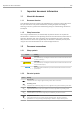
T82 Important document information 1.2.3 Symbols and notation for certain types of information Symbol Meaning Allowed Indicates procedures, processes or actions that are allowed. A0011182 Preferred Indicates procedures, processes or actions that are preferred. A0011183 Forbidden Indicates procedures, processes or actions that are forbidden. A0011184 Tip Indicates additional information. A0011193 Reference to documentation Refers to the corresponding device documentation.
Basic safety instructions T82 2 Basic safety instructions 2.
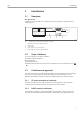
T82 Identification 3 Identification 3.1 Nameplate The right device? Compare and check the data on the nameplate of the device against the requirements of the measuring point: 5 Temperature Transmitter Made in Germany 2 4 HW 01.00.00-(1) FW 01.00.
Installation instructions T82 4 Installation instructions 4.1 Incoming acceptance, transport, storage 4.1.1 Incoming acceptance • Is the packaging or content damaged? • Is the delivery complete and is anything missing? Check the scope of delivery against your order. 4.1.2 Transport and storage • Pack the device in such a way as to protect it reliably against impact for storage (and transportation). The original packaging provides optimum protection.
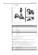
T82 Installation instructions 4.3.1 Mounting B A 7 6 5 4 8 3 2 1 1 3 2 4 C 9 1 2 3 4 5 A0019563 å2 Head transmitter mounting (three versions) Item A Mounting in a terminal head (terminal head flat face as per DIN 43729) 1 Terminal head 2 Circlips 3 Insert 4 Connection wires 5 Head transmitter 6 Mounting springs 7 Mounting screws 8 Terminal head cover 9 Cable entry Procedure mounting in a terminal head, item A: 1. Open the terminal head cover (8). 2.
Installation instructions T82 Item B Mounting in a field housing 4 Circlips 5 Field housing Procedure mounting in a field housing, item B: 1. Open the cover (1) of the field housing (5). 2. Fit the mounting springs on the mounting screws (2) and guide the screws through the side boreholes of the head transmitter (3). Then fix both mounting screws with the snap rings (4). 3. Screw the head transmitter to the field housing. 4. After wiring, (® ä 13) screw the field housing cover (1) back on.
T82 Installation instructions Thermometer design with thermocouples or RTD sensors and head transmitter: 1. Fit the thermowell (1) on the process pipe or the container wall. Secure the thermowell according to the instructions before the process pressure is applied. 2. Fit the necessary neck tube nipples and adapter (3) on the thermowell. 3. Make sure sealing rings are installed if such rings are needed for harsh environmental conditions or special regulations. 4.
Installation instructions T82 4.4 Post-installation check After installing the device, always run the following final checks: Device condition and specifications Notes Is the device undamaged (visual inspection)? - Do the ambient conditions match the device specification (e.g. ambient temperature, measuring See 'Technical data' range, etc.
T82 Wiring 5 Wiring !CAUTION ► ► ► Switch off power supply before installing or connecting the device. Failure to observe this may result in destruction of parts of the electronics. When installing Ex-approved devices in a hazardous area, please take special note of the instructions and connection schematics in the respective Ex documentation added to these Operating Instructions. The local supplier representative is available for assistance if required. Do not occupy the display connection.
Wiring T82 5.2 Connecting the sensor cables Terminal assignment of the sensor terminals (® å 5, ä 13). NOTICE When connecting 2 sensors, ensure that there is no galvanic connection between the sensors (e.g. caused by sensor elements that are not isolated from the thermowell). The resulting equalizing currents distort the measurement considerably. ► The sensors must remain galvanically isolated from one another by connecting each sensor separately to a transmitter.
T82 Wiring 21+ 2 * 2- 1+ 1 * 3 4 A0008284 Connecting the signal cable and power supply - left: installed in field housing, right: installed in terminal head å6 A B C D Terminals for HART® -protocol and power supply Internal ground terminal External ground terminal Shielded signal cable (recommended for HART® protocol) • The terminals for connecting the signal cable (1+ and 2-) are protected against reverse polarity. • Conductor cross-section: – Max. 2.5 mm2 for screw terminals – Max. 1.
Wiring T82 3 1 2 - .
T82 Operating options 6 Operating options 6.1 Overview of operation options 1 5 4 7 8 2 6 OFF 3 HW ON 1 2 4 8 16 32 64 SW ADDR SIM WRITE LOCK DISPL. 180° A0014460 å8 1 2 3 4 5 6 7 8 Operating options of the head transmitter PLC (programmable logic controller) Transmitter power supply unit (with communication resistor) Connection for HART® modems Field Communicator 375, 475 Computer with operating tool (e.g. FieldCare, AMS Device Manager, SIMATIC PDM) HART® modem, e. g.
Operating options T82 6.2 Structure and function of the operating menu 6.2.1 Structure of the operating menu Operating menu for operators and maintenances Display/operat.
T82 Operating options 6.2.2 Submenus and user roles Certain parts of the menu are assigned to certain user roles. Each user role corresponds to typical tasks within the lifecycle of the device. User role Typical tasks Menu Content/meaning Operator Tasks during operation: • Configuration of the display. • Reading measured values.
Operating options T82 6.3 Measured value display and operating elements 6.3.1 Display 1 6 2 3 4 5 7 A0008549 Optional LC display of the head transmitter å9 Item No. Function Description 1 Displays the TAG TAG, 32 characters long. 2 'Communication' symbol The communication symbol appears when read and write-accessing via the fieldbus protocol. 3 Unit display Unit display for the measured value displayed. 4 Measured value display Displays the current measured value.
T82 Operating options NOTICE ESD - electrostatic discharge. Protect the terminals from electrostatic discharge. Failure to observe this may result in destruction or malfunction of parts of the electronics. ► OFF HW ON 1 2 4 8 16 32 64 SW ADDR ACTIVE SIM WRITE LOCK DISPL. 180° 1 1: Connection to head transmitter 2 2: DIP switch (1 - 64, SW/HW, ADDR and SIM = simulation mode) no function for this head transmitter 3: DIP switch (WRITE LOCK = write protection; DISPL.
Operating options T82 6.4.2 AMS Device Manager Function scope Program from Emerson Process Management for operating and configuring measuring devices via the HART® protocol. Source for device description files See data (® ä 23). 6.4.3 SIMATIC PDM Function scope Program from Siemens for the operation, configuration, maintenance and diagnosis of intelligent field devices via the HART® protocol. Source for device description files See data (® ä 23). 6.4.
T82 Integrating the transmitter via the HART® protocol 7 Integrating the transmitter via the HART® protocol Version data for the device Firmware Version 01.00.
T82 Integrating the transmitter via the HART® protocol Device variable code Measured value 2 Device temperature 3 Average of sensor 1 and sensor 2 4 Difference between sensor 1 and sensor 2 5 Sensor 1 (backup sensor 2) 6 Sensor 1 with switchover to sensor 2 if a limit value is exceeded 7 Average of sensor 1 and sensor 2 with backup The device variables can be queried by a HART® master via HART® command 9 or 33.
T82 Commissioning 8 Commissioning 8.1 Function check Before commissioning the measuring point make sure that all final checks have been carried out: • Checklist “Post-installation check”, (® ä 12) • Checklist “Post-connection check”, (® ä 13) 8.2 Switching on the transmitter Once the final checks have been successfully completed, it is time to switch on the supply voltage. The transmitter performs a number of internal test functions after power-up.
Accessories T82 10 Accessories Various accessories, which can be ordered separately from your supplier, are available for the device. Detailed information on the order code in question can be obtained from your service organization.
T82 Diagnostics and troubleshooting 11 Diagnostics and troubleshooting 11.1 Troubleshooting Always start troubleshooting with the checklists below if faults occur after start up or during operation. This takes you directly (via various queries) to the cause of the problem and the appropriate remedial measures. Due to the its design, the device cannot be repaired. However, it is possible to send the device in for examination. See the information in the "Return" section (® ä 32).
Diagnostics and troubleshooting T82 Problem Failure current (≤ 3.6 mA or ≥ 21 mA) Possible cause Remedy The cable resistance of the sensor (2wire) was not compensated. Compensate the cable resistance. Offset incorrectly set. Check offset. Faulty sensor. Check the sensor. RTD connected incorrectly. Connect the connecting cables correctly (terminal diagram). Incorrect device programming (e.g. number of wires). Change the Connection type device function. Incorrect programming.
T82 Diagnostics and troubleshooting 11.2 Diagnostics events 11.2.1 Displaying diagnostic events 1 A 2 1 B 3 A0014837 A B 1 2 3 Display in the event of a warning Display in the event of an alarm Status signal in the header The display alternates between the primary measured value and the status - indicated by the appropriate letter (M, C or S) - plus the defined error number.
Diagnostics and troubleshooting T82 Diagnostics event and event text The fault can be identified using the diagnostics event. The event text helps you do so by providing information about the fault. Diagnostics event Status signal Event number Event text ¯ ¯ ¯ 042 Sensor corroded Example 3-digit number If two or more diagnostic messages are pending simultaneously, only the message with the highest priority is shown.
T82 Diagnostics and troubleshooting Diagno stics number Event text Remedial measures Status signal from the factory Event level from the factory Changeab le in 102 Sensor value too high 1. Check process temperature. 2. Check sensor. 3. Check sensor type. F Alarm 104 Backup active 1. Check electrical connection sensor 1. 2. Replace sensor 1. 3. Check connection type. M Warning 105 Calibration interval 1. Execute calibration and reset calibration interval. 2. Switch off calibration counter.
Diagnostics and troubleshooting T82 Diagno stics number Event text Status signal from the factory Event level from the factory Changeab le in Remedial measures Diagnostics for the process 803 Current loop 1. Check wiring. 2. Replace electronics. F Alarm 842 Process limit Check the adjusted range of the analog output. M Warning 1) F, S 925 1) Device temperature Ensure ambient temperature as per specification. S Warning F Event level can be changed in: 'Alarm' or 'Warning' 11.
T82 Technical data 12 Technical data 12.1 Input Measured variable Temperature (temperature-linear transmission behavior), resistance and voltage. Type of input Two independent sensors can be connected. The measuring inputs are not galvanically isolated from each other. Type of input Designation Measuring range limits Resistance thermometer (RTD) as per IEC 60751:2008 (a = 0.
Technical data T82 The following connection combinations are possible when both sensor inputs are assigned: Sensor input 1 Sensor input 2 12.
T82 Technical data Filter 1st order digital filter: 0 to 120 s Current consumption • 3.6 to 23 mA • Minimum current consumption ≤ 3.5 mA • Current limit ≤ 23 mA Protocol-specific data Switch-on delay HART® version 6 Device address in multi-drop mode Software setting addresses 0 to 63 Write protection Hardware setting for activating write protection Device description files (DD) Information and files are available from your supplier or online at: www.hartcomm.
Technical data T82 Designation/measuring range Performance characteristics Resistance transmitters (W) 10 to 400 W 10 to 2 000 W ±0.04 W ±0.8 W 0.03 % 0.03 % Voltage transmitter (mV) –20 to 100 mV ±10 µV 0.03 % 1) % refers to the set span.
T82 Technical data Output £ 2 mA Influence of the supply voltage ≤ ±0.0025%/V, with reference to the span Long-term stability ≤ 0.1 °C/year (≤ 0.18 °F/year) or ≤ 0.05 %/year Data under reference operating conditions. % refers to the set span. The larger value is valid. Influence of ambient temperature (temperature drift) Total temperature drift = input temperature drift + output temperature drift Impact on accuracy when ambient temperature changes by 1 K (1.8 °F): Input10 to 400W Typ. 0.
Technical data T82 Altitude Up to 4000 m (4374.5 yards) above mean sea level as per IEC 61010-1, CAN/CSA C22.2 No. 61010-1 Climate class As per IEC 60654-1, Class C Humidity • Condensation permitted as per IEC 60 068-2-33 • Max. rel. humidity: 95% as per IEC 60068-2-30 Degree of protection IP 20. In the installed state, depends on the terminal head or field housing used.
T82 Technical data A0007672 Version with spring terminals. The dimensions are identical to the version with screw terminals, apart from the housing height, dimensions in mm (in). å 12 Weight Approx. 40 to 50 g (1.4 to 1.
Technical data FM approval T82 Labeling: IS / I / 1 / ABCD / T4 Ta = 85°C — Entity*; NI / I / 2 / ABCD / T4 Ta = 85°C — NIFW*; I / 0 / AEx ia IIC T4 Ta = 85°C — Entity*; *= Entity and NIFW parameters in accordance with Control Drawings (CD) Application: • Intrinsic safety • Non-incendive For connection data see table in seperate Ex documentation CSA approval (Canadian Standard Association) Labeling: Class I, Div. 1, Groups A, B, C, D Entity*; Ex ia IIC Class I, Div.
T82 Operating menu and parameter description 13 Operating menu and parameter description The following table lists all parameters the menus "Display/operation, Setup, Diagnostics and Expert" may contain. The page number refers to where a description of the parameter can be found. Depending on the device version and parametrization some parameters will not be available in a given situation. For details on the conditions refer to the "Prerequisite" category in the description of the respective parameter.
Operating menu and parameter description Setup ® Setup ® Advanced setup ® Advanced setup ® T82 Sensor ® Current output ® Sensor offset 1 (® ä 57) Sensor offset 2 (® ä 57) Corrosion detection (® ä 57) Drift/difference mode (® ä 57) Drift/difference alarm category (® ä 58) Drift/difference set point (® ä 58) Sensor switch set point (® ä 58) Output current (® ä 59) Measuring mode Diagnostics ® Diagnostics ® Diagnostics ® Diagnostics ® Diagnostics ® 42 Out of range category (® ä
T82 Diagnostics ® Diagnostics ® Operating menu and parameter description Measured values ® Simulation ® Min/max values ® Sensor n min value (® ä 67) Sensor n max value (® ä 67) Reset sensor min/max values (® ä 67) Device temperature max. (® ä 67) Device temperature min. (® ä 68) Reset device temp.
Operating menu and parameter description 1) Expert ® (® ä 71) Serial no. sensor (® ä 71) Sensor ® Sensor ® Sensor n ® Sensor n 1)® Sensor Trimming ® Linearization ® Sensor trimming (® ä 72) Sensor trimming lower value (® ä 72) Sensor trimming upper value (® ä 73) Sensor trimming min span (® ä 73) Sensor n lower limit (® ä 71) Sensor n upper limit (® ä 71) Call./v. Dusen coeff. R0, A, B, C (® ä 74) Polynom coeff.
T82 Expert ® Expert ® Expert ® Expert ® Expert ® Expert ® Operating menu and parameter description Communication ® Communication ® Diagnostics ® Diagnostics ® Diagnostics ® Diagnostics ® HART info ® HART output ® Burst mode (® ä 78) Burst command (® ä 78) Burst variable slots 0...
Operating menu and parameter description Expert ® Expert ® Expert ® Expert ® 46 Diagnostics ® Diagnostics ® Diagnostics ® Diagnostics ® T82 Measured values ® Measured values ® Simulation ® Device reset ® Order code (® ä 65) Extended order code (® ä 84) Extended order code 2 (® ä 84) Extended order code 3 (® ä 84) ENP version (® ä 84) Device revision (® ä 80) Manufacturer ID (® ä 84) Manufacturer (® ä 85) Hardware revision (® ä 85) Configuration counter (® ä 66) Sensor n va
T82 Operating menu and parameter description 13.1 "Display/operation" menu The settings for displaying the measured value on the optional plug-in display are made in the "Display/Operation" menu. The following parameters can be found in "Display/operation" and "Expert ® System ® Display". These settings do not have any effect on the output values of the transmitter. They are only used to configure how information is shown on the display.
Operating menu and parameter description Additional information T82 Value only A0014564 Value + Bargraph A0014563 Value 1 display Navigation Description Display/operation ® Value 1 display Expert ® System ® Display ® Value 1 display Use this function to select one of the measured values to be shown on the local display. The Format display parameter is used to specify how the measured values are displayed (® ä 47).
T82 Description Operating menu and parameter description Use this function to select the number of decimal places displayed for the display value. This setting does not affect the accuracy of the device for measuring or calculating the value. If Automatic is selected, the maximum possible number of decimal places is always shown on the display. Options: •x • x.x • x.xx • x.xxx • x.
Operating menu and parameter description Options: •x • x.x • x.xx • x.xxx • x.xxxx • Automatic Factory settings Automatic T82 Value 3 display Display/operation ® Value 3 display Expert ® System ® Display ® Value 3 display Navigation Description Use this function to select one of the measured values to be shown on the local display. The Format display parameter is used to specify how the measured values are displayed.
T82 Operating menu and parameter description 13.2 "Setup" menu This menu contains all the parameters that are needed to configure the basic settings of the device. The transmitter can be put into operation with this limited parameter set. n = Stands for the number of sensor inputs (1 and 2) Unit Setup ® Unit Expert ® System ® Unit Navigation Description Use this function to select the engineering unit for all the measured values.
Operating menu and parameter description Options: • Sensor 1 (connection type 1): 2-wire, 3-wire, 4-wire • Sensor 2 (connection type 2): 2-wire, 3-wire Factory settings • Sensor 1 (connection type 1): 4-wire • Sensor 2 (connection type 2): 3-wire T82 2-wire compensation n Setup ® 2-wire compensation n Expert ® Sensor ® Sensor n ® 2-wire compensation n Navigation Prerequisite An RTD sensor with a 2-wire connection type must be specified as the sensor type.
T82 Operating menu and parameter description Setup ® RJ preset value Expert ® Sensor ® Sensor n ® RJ preset value Navigation Prerequisite The Fixed value parameter must be set if the Reference junction n option is selected. Description Use this function to define the fixed preset value for temperature compensation. User input –50 to +85 °C Factory settings 0.
Operating menu and parameter description T82 Upper range value Setup ® Upper range value Expert ® Output ® Upper range value Navigation Description Use this function to assign a measured value to the current value 20 mA. The set point that can be set depends on the sensor type used in the Sensor type (® ä 51) parameter and the measured variable assigned in the Assign current output (PV) parameter. User input Depends on the sensor type and the setting for "Assign current output (PV).
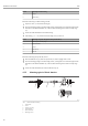
T82 Operating menu and parameter description A B D D L+ L+ 0 0 L- Lx t t x A0014782 å 13 A B D L+, Lt x Drift/difference mode Value under range Value over range Drift Upper (+) or lower (-) set point Time Diagnostics event, status signal is generated Enter access code Setup ® Advanced setup ® Enter access code Expert ® Enter access code Navigation Description Use this function to enable the service parameters via the operating tool.
Operating menu and parameter description T82 Device temperature alarm Setup ® Advanced setup ® Device temperature alarm Navigation Description Use this function to select the category (status signal) as to how the device reacts when the electronics temperature of the transmitter exceeds or falls below the limit value < -40 °C (-40 °F) or > +85 °C (+185 °F).
T82 Operating menu and parameter description "Sensor" submenu Sensor offset n n = Stands for the number of sensor inputs (1 and 2) Setup ® Advanced setup ® Sensor ® Sensor offset n Expert ® Sensor ® Sensor n ® Sensor offset n Navigation Description Use this function to set the zero point correction (offset) of the sensor measured value. The value indicated is added to the measured value. User input -10.0...+10.0 Factory settings 0.
Operating menu and parameter description Options: • Off • Out band (drift) • In band Factory settings Off T82 Drift/difference alarm category Setup ® Advanced setup ® Sensor ® Drift/difference alarm category Expert ® Sensor ® Diagnostic settings ® Drift/difference alarm category Navigation Prerequisite The Drift/difference mode parameter must be activated with the Out band (drift) or In band option.
T82 Operating menu and parameter description Additional information The threshold value is relevant if the sensor switching function is assigned to a HART® variable (PV, SV, TV, QV). Options: Depends on the sensor types selected. Factory settings 0.0 °C "Current output" submenu Adjustment of the analog output (4 and 20 mA current trimming) Current trimming is used to compensate the analog output (D/A conversion).
Operating menu and parameter description T82 Measuring mode Setup ® Advanced setup ® Current output® Measuring mode Expert ® Output ® Measuring mode Navigation Description Enables the inversion of the output signal.
T82 Operating menu and parameter description Failure current Setup ® Advanced setup ® Current output® Failure current Expert ® Output ® Failure current Navigation Prerequisite The Max. option is enabled in the Failure mode parameter. Description Use this function to set the value the current output adopts in an alarm condition. User input 21.5 to 23.0 mA Factory settings 22.
Operating menu and parameter description 13.3 T82 "Diagnostics" menu All the information that describes the device, the device status and the process conditions can be found in this group. Actual diagnostics 1 Navigation Diagnostics ® Actual diagnostics Expert ® Diagnostics ® Actual diagnostics 1 Description Use this function to display the current diagnostics message. If two or more messages occur simultaneously, the message with the highest priority is shown on the display.
T82 Display Operating menu and parameter description Hours (h) 13.3.1 "Diagnostics list" submenu Up to 3 diagnostics messages currently pending are displayed in this submenu. If more than 3 messages are pending, the messages with the highest priority are shown on the display. Information on diagnostics measures in the device and an overview of all the diagnostics message (® ä 27).
Operating menu and parameter description 13.3.2 T82 "Event logbook" submenu Previous diagnostics n n = Number of diagnostics messages (n = 1 to 5) Navigation Diagnostics ® Diagnostics list ® Previous diagnostics n Expert ® Diagnostics ® Diagnostics list ® Previous diagnostics n Description Use this function to display the diagnostics messages that occurred in the past. The last 5 messages are listed in chronological order. Display Symbol for event behavior and diagnostic event.
T82 Operating menu and parameter description 13.3.3 "Device information" submenu Device tag (® ä 56) Serial number Navigation Diagnostics ® Device information ® Serial number Expert ® Diagnostics ® Device information ® Serial number Description Use this function to display the serial number of the device. It can also be found on the nameplate. Display Max.
Operating menu and parameter description Description T82 Use this function to display the order code of the device. It can also be found on the nameplate. The order code is generated from the extended order code, which defines all the device features of the product structure. In contrast, the device features cannot be read directly from the order code. Uses of the order code • To order an identical spare device. • To identify the device quickly and easily, e.g. when contacting the supplier.
T82 Operating menu and parameter description "Min/max values" submenu Sensor n min value n = Stands for the number of sensor inputs (1 and 2) Diagnostics ® Measured values ® Min/max values ® Sensor n min value Expert ® Diagnostics ® Measured values ® Min/max values ® Sensor n min value Navigation Description Use this function to display the minimum temperature measured in the past at sensor input 1 or 2 (peakhold indicator).
Operating menu and parameter description Description T82 Use this function to display the maximum electronics temperature measured in the past (maximum indicator). Device temperature min. Diagnostics ® Measured values ® Min/max values ® Device temperature min. Expert ® Diagnostics ® Measured values ® Min/max values ® Device temperature min. Navigation Description Use this function to display the minimum electronics temperature measured in the past (maximum indicator). Reset device temp.
T82 Additional information Operating menu and parameter description The simulation value is defined in the Value current output parameter. Value current output Navigation Diagnostics ® Simulation ® Value current output Expert ® Diagnostics ® Simulation ® Value current output Additional information The Simulation current output parameter must be set to On. Description Use this function to set a current value for the simulation.
Operating menu and parameter description 13.4 T82 "Expert" menu The parameter groups for the Expert setup contain all the parameters of the "Display/operation", "Setup" and "Diagnostics" operating menus, as well as other parameters that are solely reserved for experts. 13.4.1 "System" submenu Damping Expert ® System ® Damping Navigation Description Use this function to set the time constant for current output damping. User input 0 to 120 s Factory settings 0.
T82 Operating menu and parameter description Device temperature alarm (® ä 56) Navigation Expert ® System ® Device temperature alarm (parameter) "Display" submenu (® ä 47) 13.4.2 "Sensor" submenu Serial no. sensor Navigation Expert ® Sensor ® Sensor n ® Serial no. sensor Description Use this function to enter the serial number of the connected sensor.
Operating menu and parameter description T82 Sensor trimming does not adapt the measuring range. It is used to adapt the sensor signal to the linearization stored in the transmitter. Procedure 1. Start ß 2. Set the Sensor trimming parameter to the User trim settings setting. ß 3. Using a water/oil bath or a furnace, bring the sensor connected to the transmitter to a known and stable temperature. A temperature which is close to the set start of the measuring range is recommended. ß 4.
T82 Operating menu and parameter description User input Depends on the selected sensor type and the assignment of the current output (PV). Factory settings -200 °C Sensor trimming upper value Navigation Expert ® Sensor ® Sensor n ® Sensor trimming ® Sensor trimming upper value Prerequisite The User trim settings option is enabled in the Sensor trimming parameter. Description Upper point for linear characteristic calibration (this affects offset and slope).
Operating menu and parameter description T82 8. If special linearization is also used for a second sensor, repeat steps 2 to 6. ß 9. End Sensor n lower limit Navigation Expert ® Sensor® Sensor n ® Linearization ® Sensor n lower limit Prerequisite The RTD platinum, RTD poly nickel or RTD polynomial copper option is enabled in the Sensor type parameter. Description Use this function to set the lower calculation limit for special sensor linearization. User input Depends on the sensor type selected.
T82 Operating menu and parameter description Call./v. Dusen coeff. A, B and C Navigation Expert ® Sensor ® Sensor n ® Linearization ® Call./v. Dusen coeff. A, B, C Prerequisite The RTD platinum (Callendar/Van Dusen) option is enabled in the Sensor type parameter. Description Use this function to set the coefficients for sensor linearization based on the Callendar/Van Dusen method. Factory settings • A: 3.910000e-003 • B: -5.780000e-007 • C: -4.180000e-012 Polynomial coeff.
Operating menu and parameter description Description T82 Option to control the calibration counter. • The countdown duration (in days) is specified with the Calibration counter start value parameter. • The status signal issued when the limit value is reached is defined with the Calibration counter alarm category parameter.
T82 Operating menu and parameter description 13.4.3 "Output" submenu Measuring mode Navigation Expert ® Output ® Measuring mode Description Enables the inversion of the output signal. Additional information • Standard The output current increases with increasing temperatures • Inverse The output current decreases with increasing temperatures Options: • Standard • Inverse Factory settings Standard 13.4.
Operating menu and parameter description T82 User input • For a system in accordance with HART 5.0: 0 to 15 • For a system in accordance with HART 6.0: 0 to 63 Factory settings 0 Additional information The measured value can only be transmitted via the current value is the address is set to "0". The current is fixed at 4.0 mA for all other addresses (Multidrop mode). No. of preambles Expert ® Communication ® HART configuration ® No.
T82 Operating menu and parameter description Options: • Command 1 Read out the primary variable • Command 2 Read out the current and the main measured value as a percentage • Command 3 Read out the dynamic HART variables and the current • Command 9 Read out the dynamic HART variables including the related status • Command 33 Read out the dynamic HART variables including the related unit Factory settings Command 2 Additional information Commands 1, 2, 3 and 9 are universal HART commands.
Operating menu and parameter description T82 Configuration changed Navigation Description Expert ® Communication ® HART configuration ® Configuration changed Indicates the change of configuration via a primary or a secondary master. Reset Configuration Changed Flag Navigation Description Expert ® Communication ® HART configuration ® Reset Configuration Changed Flag Reset of the information Configuration changed via a primary or secondary master.
T82 Operating menu and parameter description HART descriptor Navigation Expert ® Communication ® HART info ® HART descriptor Description Use this function to define a description for the measuring point.
Operating menu and parameter description T82 "HART output" submenu Assign current output (PV) Navigation Expert ® Communication ® HART output ® Assign current output (PV) Description Use this function to assign a measured variable to the primary HART value (PV). Options: • Sensor 1 (measured value) • Sensor 2 (measured value) • Device temperature • Average of the two measured values: 0.
T82 Navigation Description Operating menu and parameter description Expert ® Communication ® HART output ® SV Use this function to display the secondary HART value. Assign TV Navigation Expert ® Communication ® HART output ® Assign TV Description Use this function to assign a measured variable to the tertiary HART value (TV).
Operating menu and parameter description 13.4.5 T82 "Diagnostics" submenu "Device information" submenu Extended order code 1-3 Navigation Description Expert ® Diagnostics ® Device information ® Extended order code 1-3 Use this function to display the first, second and/or third part of the extended order code. On account of length restrictions, the extended order code is split into a maximum of 3 parameters.
T82 Factory settings Operating menu and parameter description 17 Manufacturer Navigation Description Expert ® Diagnostics ® Device information ® Manufacturer Use this function to display the name of the manufacturer. Hardware revision Navigation Description Expert ® Diagnostics ® Device information ® Hardware revision Expert ® Communication ® HART info ® Hardware revision Use this function to display the hardware revision of the device.
Index T82 Index 0…9 2-wire compensation (parameter) . . . . . . . . . . . . . . . . . . 52 A Access status tooling (parameter) . . . . . . . . . . . . . . . . . . 55 Actual diag channel . . . . . . . . . . . . . . . . . . . . . . . . . . . 63 Actual diagnostics . . . . . . . . . . . . . . . . . . . . . . . . . . . . 63 Actual diagnostics 1 . . . . . . . . . . . . . . . . . . . . . . . . . . . 62 Actual diagnostics count . . . . . . . . . . . . . . . . . . . . . . . . 63 Advanced setup (submenu) . . . . .
Index T82 M Mains filter (parameter) . . . . . . . . . . . . . . . . . . . . . . . . 70 Manufacturer . . . . . . . . . . . . . . . . . . . . . . . . . . . . . . . 85 Manufacturer ID (parameter) . . . . . . . . . . . . . . . . . . . . . 84 Measured values (submenu) . . . . . . . . . . . . . . . . . . 66, 85 Measuring mode (parameter) . . . . . . . . . . . . . . . . . . 60, 77 Min/max values (submenu) . . . . . . . . . . . . . . . . . . . . . 67 N Nameplate . . . . . . . . . . . . . . . . . . . . . . . . .
Pyromation, Inc. 5211 Industrial Road Fort Wayne, IN 46825 USA Tel: (260) 484-2580 Fax: (260) 482-6805 or (800) 837-6805 www.pyromation.com BA01139O/09/EN/13.