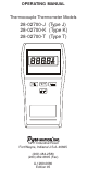
OPERATING MANUAL Thermocouple Thermometer Models 28-02700-J (Type J) 28-02700-K (Type K) 28-02700-T (Type T) 5211 Industrial Road Fort Wayne, Indiana U.S.A.
CERTIFICATE OF CONFORMANCE This thermometer was calibrated using equipment traceable to the National Institute of Standards and Technology (NIST). This instrument conforms to NIST monograph 175 revised to ITS-90. The accuracy of the thermometer at the time of calibration was within specifications stated in the operating manual. Model No.
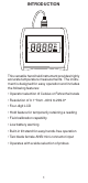
INTRODUCTION This versatile hand-held instrument provides highly accurate temperature measurements. The instrument is designed for easy operation and includes the following features: • Operator selection of Celsius or Fahrenheit scale • Resolution of 0.1° from –99.9 to 299.
SAFETY PRECAUTIONS INSTRUMENT IS WARNING THIS DESIGNED TO ACCEPT LOW LEVEL SIGNALS SUPPLIED BY STANDARD THERMOCOUPLES. UNDER NO CIRCUMSTANCES SHOULD THE INPUT VOLTAGE EXCEED THE SPECIFIED 50V RMS. DO NOT USE OR STORE CAUTION THIS INSTRUMENT IN MICROWAVE OVENS OR ANY ABNORMALLY HOT OR COLD AREAS. WEAK BATTERIES SHOULD CAUTION NOT BE LEFT IN THE INSTRUMENT. DEAD BATTERIES CAN LEAK AND CAUSE DAMAGE TO UNIT. VOLTAGES PRESENT AT DANGER THE THERMOCOUPLE MAY ALSO BE PRESENT AT THE BATTERY TERMINALS.
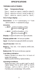
SPECIFICATIONS THERMOCOUPLE PROBES Type Temperature Range Type J: –200°C to 1000°C (–328°F to 1832°F ) Type K: –250°C to 1372°C (–418°F to 2501°F ) Type T: –250°C to 400°C (–418°F to 752°F ) Out of range display: - - - Resolution: 0.1°/1° autoranging, 0.1° from –99.9° to 299.9°, 1° outside this range. Accuracy > –99.9°: +(0.2% of reading +0.5°C) +(0.2% of reading +0.9°F) < –99.9°: +(0.25% of reading, +1°C) +(0.25% of reading +2°F) Display: 4-digit LCD with 0.5 in high numerals. Display update rate: 0.
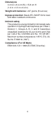
Dimensions 3 cm D x 8.4 cm W x 15.8 cm H (1.2 in x 3.3 in x 6.2 in) Weight with batteries: 227 grams (8 ounces) Ingress protection: Meets IEC-529 IP-54 for dust and water-resistant enclosures. Intrinsic safety This product is energy limited for intrinsically safe operation in hydrogen atmospheres per Class I, Division 1, Groups A, B, C and D hazardous (classified) locations for UL per UL913 and CSA per C22.2 No. 0-M1982 and No. 157-M1987. Maximum surface temperature: 135°C (T4); UL file No. E182612 (1997).
BATTERY INSTALLATION AND REPLACEMENT CAUTION WEAK BATTERIES SHOULD NOT BE LEFT IN THE INSTRUMENT. DEAD BATTERIES CAN LEAK AND CAUSE DAMAGE TO UNIT. PRESENT AT DANGER VOLTAGES THE THERMOCOUPLE MAY ALSO BE PRESENT AT THE BATTERY TERMINALS. ALWAYS DISCONNECT THE THERMOCOUPLE WHEN CHANGING BATTERIES. TO PREVENT IGNITION OF WARNING A HAZARDOUS ATMOSPHERE, BATTERIES MUST ONLY BE CHANGED IN AN AREA KNOWN TO BE NON-HAZARDOUS.
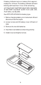
If battery indicator turns on, battery life is approximately 8 to 10 hours. The battery indicator will start blinking with less than 1 hour of life remaining. AT THIS POINT, BATTERY MUST BE CHANGED. IF BATTERY VOLTAGE GOES TOO LOW, DISPLAY WILL GO BLANK. See SPECIFICATIONS for battery type. 1. Before changing battery, turn instrument off and disconnect thermocouple. 2. Loosen screw and lift battery cover off back of case. 3. Remove the two AA batteries. 4. Insert two new batteries observing polarity. 5.
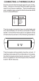
CONNECTING A THERMOCOUPLE Use the correct thermocouple type for your instrument. Using an incorrect thermocouple type will result in erroneous readings. Thermocouples are color coded by type using the North American ANSI Color Code as follows: TYPE J K T COLOR Black Yellow Blue Thermocouple connectors have one wide blade and one narrow blade. Do not force connector in backwards. Connect thermocouple to receptacle at top of instrument as shown in the following illustration.
8
9
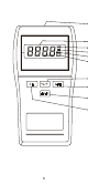
OPERATION Note: Be sure the thermocouple you are using matches the instrument setting indicated on the unit. 1. Press the ON/OFF key. The thermometer performs a self-test and all display digits and indicators, as shown below, should remain on for approximately two seconds. 2. If a thermocouple is not connected or if the thermocouple is defective, the display will indicate OPEn. 3. Select °C or °F by pressing the °C/°F key. Temperature scale can be switched at any time.
FIELD CALIBRATION The thermometer is factory calibrated and does not require calibration before use. The CAL function allows single point calibration of the thermometer, at 0°C (32°F) to compensate for thermocouple offset error. It is not necessary to perform a field calibration to obtain specified meter accuracy. Use the field calibration feature to improve thermometer/ probe accuracy or to compensate for thermocouple drift. 1. Follow steps 1 through 4 in OPERATION section. 2.
FIELD CALIBRATION LOCKOUT AND RE-ENABLE The calibration lockout feature, prevents any field calibration changes. The lockout remains in effect until a lockout re-enable has been performed. Use the following procedures to lockout or re-enable the field calibration operation. Lockout Procedure 1. Turn the thermometer off. 2. Simultaneously press and hold the CAL and the °C/°F keys down and momentarily press the ON/ OFF key. Continue to hold the CAL and °C/°F keys for at least 5 seconds. Re-Enable Procedure 1.
MAINTENANCE Properly used, the thermometer should maintain calibration indefinitely and not require service other than occasional cleaning of the housing and changing of the batteries. CLEANING TO PREVENT IGNITION OF WARNING A HAZARDOUS ATMOSPHERE BY ELECTROSTATIC DISCHARGE, CLEAN WITH DAMP CLOTH. Do not clean with abrasives or solvents. Use mild detergents, never immerse nor use excessive fluid. BATTERIES If there is no display when the thermometer is turned on, check condition of the two AA batteries.
SERVICE OF COMWARNING SUBSTITUTION PONENTS MAY IMPAIR INTRINSIC SAFETY. LA SUBSTITUTION DE AVERTISSEMENT COMPOSANTS PEUT COMPROMETTRE LA SECURITE INTRINSEQUE. There are no internal adjustments or user replaceable parts. If “Err” followed by the numbers 1 through 9 is displayed (see example below) return unit for service. Note that “Err” alone may be displayed during improper field calibration. Note: Serial number label is located inside battery compartment. A-1925-32 Rev. E Printed in U.S.A.
15
WARRANTY The Manufacturer warrants this product to be free from significant deviations from published specifications. If repair or adjustment is necessary within the warranty period, the problem will be corrected at no charge if it is not due to misuse or abuse on your part as determined by the Manufacturer. Repair costs outside the warranty period, or those resulting from product misuse or abuse, may be invoiced to you. The warranty period for this product is noted on the Warranty Card.