
Operating instructions
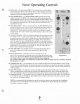
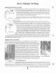

Stove Operating Controls
,
?-
Start Switch
-
The push-bunon START switch activates the convection blower
?
and the combustion blower. If the exhaust does not reach operating temperature
i
within 30 minutes, the stove will automatically shut down. The blowers can be
restarted by pushing the START switch again.
"3r-,.,
,
""
Auger On/OffSwitch -The AUGER ON/OFF switch activates the fuel feed
(auger) motor only. The START switch has to be activated to give power to the
AUGER
ON/OFF SWITCH. When the AUGER ON/OFF SWITCH switch
is
turned
0
.
.
off, the fuel feed will stop and the blowers will continue to operate until the stove
has cooled down sufficiently
(up to 45 minutes); then the stove blowers will
automatically turn off.
Heat
Output
Switch
-
When on manual operation, the HEAT OUTPUT switch
provides the ability to burn at five burn rates. Pressing the heat output switch will
increase the setting by one position. (After setting
#5 it will revert to
#I).
The
HEAT OUTPUT switch alters the fuel feed rate and the combustion air supply
simultaneously. The control
is
preset to provide the optimum ratio of fuel and air
m
,,:a?>,
,
,:
"^
.:.
at each setting.
.-
Thermostat Operation -While on thermostat operation, the stove operates under
1
<.
.*
,.,
two senings. There
is
a "pilot" (low) sening and a "demand" (high) setting. If your
thermostat senses the room heat to be higher than your selected temperature, the
thermostat will set the stove to the "pilot" or low setting. This
is
equivalent to
physically setting the stove on HEAT OUTPUT setting
#l.
If your room tempera-
ture is lower than the selected thermostat temperature, the thermostat will operate
,AI<:I.:u
/
the stove at the HEAT OUTPUT switch sening you have manually selected. Use a
HEAT OUTPUT switch setting from
#2
through
#5.
The heat output light will
flash on and off during thermostat operation.
9
;.rl
Auger "On" Light
-
The red light on the control panel indicates that there
is
1
"
r,3,-.
power to the auger motor. Under normal operation, this light will blink
b
.
n
on and off.
Blower Speedswitch -This button on the control panel controls the
"'x'R!Ii"!'$7RIFS
Xi
speed of the convection fan. Turning up the fan will increase the amount of heat
Control Board
into the room. For the best efficiency use the maximum blower speed when high
heat output settings are used. The control will limit the blower settings to
2
&
3
at heat output settings
4
&
5
respectively. In other words, when heat output is set to
5,
the blower will scroll
through speeds
3,4
and
5.
Combustion Fan Trim -The Combustion Fan Trim is located just above the Heat Output Selector switch. Turning
the Trim Control counterclockwise will decrease the amount of combustion air entering the burn grate. Turning the
control clockwise will increase the amount of combustion air entering the burn grate. The Trim Control
is
factory set
at the
(0) position.
Auger Trim Control-The Auger Trim Control
is
located just above the Auger OnIOff switch. Turning the Trim
Control counterclockwise will decrease the amount of fuel delivered to the burn grate. Turning the control clock
wise will increase the amount of fuel delivered to the burn grate. The trim control
is
factoiy set at the (0) position.
Convection Fan Trim -The convection fan trim
is
located on the backside of the control panel. This can be used
to eliminate fan noise by trimming fan speed slightly above or below a noise band. It can also increase air circula-
tion velocity on
#5
setting if required.
NOTE:
It
is
recommended that the damper be used to fine tune your stove to your particular fuel
&
installation,
(see
page
8).
It is also recommended that you contact your Whitfield Dealer before adjusting the combustion,
convection or auger trim controls.