OUEST PLUS A Owners Manual Operating Instructions - SAVE THESE INSTRUCTIONS - I THIS STOVE MUST BE PROPERLY INSTALLED AND OPERATED IN ORDER TO PREVENT THE POSSIBILITY OF A HOUSE FIRE. PLEASE READ 1-HIS ENTIF:E OWNER'S MANUAL BEFORE INSTALLING AND USING YOlJR WHITFIELD PELLET TOVE. FAILURE TO FOLLOW THESE INSTRUCTIONS COULD RESULT IN PROPERTY DAMAGE, BODILY INJURYOR iVEN DEA-TH. CONT,ACT YOU17 LOCAL BUILDING OR FIRE 0FFICIAI.S TO OBTAIN A PERMIT AND INFORMATION . . . . ... .. .-- . . . . .
Congratulations on the purchase of your Whitfield Quest Plus Pellet Stove! When you purchased your Whitfield stove, you joined the ranks of thousands of concerned individuals whose answer to their home heating system reflects their concern for aesthetics, efficiency and our environment. We extend our continued support to help you achieve the maximum benefit and enjoyment available from your pellet stove. Please familiarize yourself with this Owner's Manual before installing your Whitfield stove.
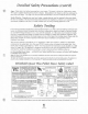
Table Of Contents Safety Precautions ................................................. 4 Installation Disclaimer . . . . . . . . . . . . . . . . . . . . . . . . . . . . . . . . . . . . . . . . . . 5 Detailed Safety Precautions . . . . . . . . . . . . . . . . . . . . . . . . . . . . . . . . . . . . 4-5 Safety Testing . . . . . . . . . . . . . . . . . . . . . . . . . . . . . . . . . . . . . . . . . . . . . . . . . . . 5 Whitfield Quest Plus Stove Safety Label . . . . . . . . . . . . . . . . . . . . . . . . .
Table Of Contents (Cont'd) .c Stove lnstallafion Stove Installation Check List . . . . . . . . . . . . . . . . . . . . . . . . . . . . . . . . . . . . . . 14 Pre-Installation Assembly . . . . . . . . . . . . . . . . . . . . . . . . . . . . . . . . . . . . . . . . 15 Stove Installation Configurations Floor Protection . . . . . . . . . . . . . . . . . . . . . . . . . . . . . . . . . . . . . . . . . . . . . . . 16 Clearances to Combustibles . . . . . . . . . . . . . . . . . . . . . . . . . . . . . . . . . .
Safety Precautions Safety Notice 7 THlS STOVE MUST BE PROPERLY INSTALLED AND OPERATED I N ORDER TO PREVENT THE POSSIBILITY OF A HOUSE FIRE. PLEASE READ THlS ENTIRE OWNER'S MANUAL BEFORE INSTALLING AND USING YOUR WHITFIELD PELLET STOVE. FAILURE TO FOLLOW THESE INSTRUCTIONS COULD RESULT IN PROPERTY DAMAGE, BODILY INIURY OR EVEN DEATH. CONTACT YOUR LOCAL BUILDING OR FIRE OFFICIALS TO OBTAIN A PERMIT AND INFORMATION O N ANY INSTALLATION RESTRICTIONS AND INSPECTION REQUIREMENTS I N YOUR AREA.
Detailed Safety Precautions (cont 'd) "F-. - Auger Pellet fuel i s fed to the burn grate by a screw auger. This auger is driven by a high torque motor. The auger is capable of doing serious harm to fingers. Keep pellets in the hopper at all times and keep fingers away from auger. The auger can start and stop automatically at any time while the stove is running. - Smoke Detector Depending on your local codes, a smoke detector may be required in the room where the stove is installed.
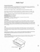
Pellet Fuel General Information Using the UltraGrate burn system, the Whitfield Quest Plus has been designed to burn wood residue pellets with up to 3% ash content. Agricultural pellets (i.e... Corn, alfalfa etc.) are not permitted to be burned in the stove. Dirty fuel will adversely affect the performance of the stove. Caution: The use o f unapproved, dirty, wet and/or high salt content fuel will void the warranty! Wood pellets manufactured to the Pellet Fuels Institute (P.F.I.
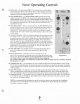
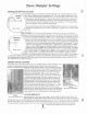
Stove Operating Controls ,?- Start Switch - The push-bunon START switch activates the convection blower and the combustion blower. If the exhaust does not reach operating temperature within 30 minutes, the stove will automatically shut down. The blowers can be restarted by pushing the START switch again. Auger On/OffSwitch -The AUGER ON/OFF switch activates the fuel feed (auger) motor only. The START switch has to be activated to give power to the AUGER ON/OFF SWITCH.
fj) Stove Damper Settings FREESTAND STOVE DAMPER I starting >\ The "push-pul1"damper rod is located on the lower right side of the Freestand model stove. The proper damper setting, to use as a starting point, is 2". It is set by pulling the damper out all the way and measuring the distance between the side panel and the inside surface of the set collar. If adjustment is required, loosen the set screw on the set collar, with the allen wrench provided. The collar will now slide freely on the damper rod.
Operating instructions p Manual Lighting Procedure: If Priming Is Required 1 . Fill the hopper with recommended pellet fuel and plug the stove into the wall outlet. 2. Press the Start switch on the control panel. This will activate both blowers. Press the Auger ON/Off switch on the control panel. This will activate the auger motor. Next, press the heat output switch t o position #5 (maximum feed rate). 3.
General Operating Considerations Proper Burn Characteristics: The flame in your stove should be bright yellow under normal operation. If the flame becomes lazy with a reddishlorange color, the damper position may need to be changed to provide more combustion air. Excessive amounts of flyash built-up in the grate, clinkers in the grate, or leakage of air (if the grate i s not properly seated) will starve the fire for air. (See ROUTINE MAINTENANCE for information on cleaning the stove).
Thermostat Installation .* NOTE: ALWAYS DISCONNECT POWER BEFORE PERFORMING THE THERMOSTAT INSTALLATION. To Install A Wall 1 . Check the type of thermostat you are about to install, Solid State Electrical thermostats are NOT approved for use with the Quest Series pellet stoves. Consult your authorized Whitfield Dealer for more details. 2. Unplug your stove from the wall outlet 3. Locate the thermostat connection block on the back of the freestand stove, and on the left side of an insert stove. 4.
Routine Cleaning NOTE: STOVE WILL NEED T O BE SHUT OFF A N D COOLED E N O U G H T O HANDLE BEFORE ROUTINE CLEANING IS PERFORMED. ALWAYS DISCONNECT POWER BEFORE D O I N G A N Y ROUTlNE CLEANING. The following areas need t o b e inspected during Routine Cleaning: Burn Grate Ash Slide Plates (Free Standing Model Only) Ash Pan ib Heat Exchanger Tubes Burn Crate:The burn grate should be inspected periodically to assure that the air holes have not become clogged with ash or clinkers.
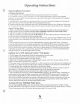
Routine Cleaning & Maintenance (cont.) )" EXHAUST DUCTS / Inspect the exhaust ducts periodically and clean when necessary. Fly ash will accumulate at all bends in the exhaust system. Based on this I inspection, derermine how often, and to what extent, the exhaust system will need to be cleaned. Note: Large amounts of fly ash build- I I ! ' up will restrict combustion air flow and reduce the stove's efficiency.
Stove Installation Stove /nsfallafion Checklist Check off each item as you go through your installation. As part of the installation process: It i s strongly recommended that you have an Authorized Whitfield Dealer install your stove. If you install the stove yourself, you should review your installation plan with the Authorized Whitfield Dealer. a a Read the ENTIRE Stove Installation section first.
Pre-lnstallation Assembly #- 1. After removing the packaging from the stove, lift the hopper lid, and remove all pre-packaged items that were shipped in the hopper. Also open the stove door and remove all pre-packaged items. 2. Using a 7116" socket or open end wrench, remove the two bolts from the bottom that secure the stove to the wooden pallet. 3. If your stove is a freestanding model, remove the pedestal from its box and place it beside the stove. With a helper, lift the stove onto its pedestal base.
Stove lnstallation Assembly Your Whitfield Quest Plus May Be Installed As: A freestanding unit with a pedestal placed on a noncombustible floor pad. A mobile home heater placed on a non-combustible floor pad, with a source of outside air, bolted down and electrically grounded to the chassis of the home. Floor Protection Your Whitfield pellet stove must be installed on a non-combustible protective floor pad of minimum 318" thickness material or a masonry hearth.
Stove Vent Pipe/ln take Installation IT IS RECOMMENDED THAT ONLY A N AUTHORIZED DEALER INSTALL YOUR PELLET STOVE. THE FOLLOWING INSTALLATION GUIDELINES MUST BE FOLLOWED T O ENSURE CONFORMITY W I T H BOTH THE SAFETY LISTING OF THE STOVE A N D LOCAL BUILDING CODES. General guidelines for installing the exhaust system: A 3 or 4 inch listed type "L" pellet vent exhaust system must be used for freestanding installations and attached (and sealed) to the pipe connector provided on the back of the stove.
Determining Equivalent Pipe Length "! To determine whether a 3" or 4" exhaust system is required for your installation, review the sample ~nstallationbelow. Fill out the top chart, and calculate your total equivalent pipe length. Afier you have the total equivalent pipe length, use the chart at the bottom of the page to determine if your installation requires 3" or 4" exhaust pipe. I Type of Pipe I # of Elbows or Feet of pipe I I Equivalent Feet I Total Equivalent Feet I w 30 -- A- 90 Deg.
Installing Your Freestanding Pellet Stove P STANDARD HORIZONTAL EXHAUST INSTALLATION 1. Locate the proper position for the listed type "L" wall thimble. Avoid cutting wall studs when installing your pipe. Use a saber saw or key hole saw to cut the proper diameter hole through the wall to accommodate the wall thimble. Use extreme caution to avoid cutting into power lines within the wall of the home. The hole size will depend on the brand of pellet vent that you are using.
freestand Stove Dimensions / I Freestand Dimensions Plus or Minus 1/4" -
Insta//ation Configurations I NONEOMBUSTISLE Hearth Pad (3/8" Minimum Thickness) .::.:, r'.... 0 9 ,.....,..., ..... : :: . ,.. : ; : \-.*-:f % XI*<<< 3" MinimumBetween WaN and Pipe , .-i Standard Horizontal lnstallafions C NOTE: I f you vent to the Right Wall, the vent pipe must maintain a 3" clearance parallel to the left wall.
lnstalla tion Configurations (Cont'd) Venting Options The Quest Plus may be connected to an existing flue or by installing listed type "L" vent pipe. If a liner i s run all the way to the top of the existing chimney, the existing flue should be sealed with a steel plate. Start vertical run with a Tee at the back of the stove. Other options are illustrated below. ;"creaser lnterior Vertical Vent thru Interior Vertical Vent into Existing Class A Chimney. = : = : .-, .
Mobile Home Installation . p*. I N ADDITION TO THE STANDARD INSTALLATION INSTRUCTIONS, THE FOLLOWING INSTRUCTIONS MAY BE REQUIRED BY LOCAL, STATE OR FEDERAL BUILDING CODES: 0 Stove must be permanently bolted t o the floor. Stove must have a permanent outside a Stove must be permanently electrically chassis of the home. The location selected stove must be dedicated for this purpose. Refer t o page 17 for list of commonly used vent components.
Installing Your Insert Pellet Stove INSERT STOVE VENTING A 3" single-wall, stainless steel flexible or rigid exhaust pipe may be used for insert installations in place of double-wall, type "L" vent. The pipe should be connected to the supplied clean-out tee. High-temperature silicone sealant should be used at the vent pipe connections to ensure a "gas-tight" seal. When venting through an existing chimney (masonry or factory built) the chimney must be cleaned.
Insert Stove Dimensions (Figure 24)-Insert Pipe Adapter Connection - (Figure 25)-Front View of Insert Contact your dealer for further assistance or information on installing your Whitfield Quest Insert.
Insert Stove Dimensions (cont.
Quest Plus lnsert Exhaust Connection FLEX LINER INSTALLATION W I T H COUPLER .@ Coupler Part Number: 13.820134 Flex Liner .- A Flex Liner may be attached to the top of the Single Wall Tee using the Coupler. Use RTV on the inside of the Tee, slide the couple in place, (112 way), and use TEK screws to secure. Apply RTV on the outside of the exposed section of the Coupler. Slide the Flex down over the coupler and use TEK screws to attach. Note: An air tight seal must be made at this junction.
Installing Your Insert Pellet Stove VENTING INTO AN EXISTING CHIMNEY 53 -RAIN CAP f * INSERT STOVE VENTED INTO EXISTING CHIMNEY The Quest insert may be installed in a masonry or factory built fireplace as shown below. When installing into the existing chimney, the exhaust venting system should be extended to the top of the chimney as shown below. However. If the vent pipe is not extended to the top of the chimney, it must extend a minimum of 18 inches ahove the chimney damper.
Routine Maintenance U N P L U G STOVE BEFORE PERFORMING A N Y MAINTENANCE W O R K The following areas need to be inspected as part of routine maintenance: Door Rope Gasket: The condition of the rope gasket around the door and windows should be checked periodically and replaced or . .~fnecessary. A one inch strip of paper may be repalred i 1 used to perform a test of the integrity of the door seal. II Close the door on the paper in several different locations i and pull.
APPENDIX A TROUBLE-SHOOTING Unplug Stove Before Performing any Maintenance work Fire burns with a lazy be obstructing the primary air dow gets sooted up. Change to a better grade of fuel if Check that the damper has been Check that the heat exchange tubes are not coated with ash. Clean internal exhaust ducts. Check gasket seal around the door. Use a thin strip of paper, 1 in. wide. Open the door and close it on the paper strip. A slight friction should be felt when the paper strip i s pulled.
APPENDIX A TROUBLE-SHOOTING (CONT'D ...) Unplug Stove Before Performing any Maintenance work lower burn rates) then the high limit snap switch should be replaced by your certified Whitfield dealer. sive 90" bends, long horizontal runs 4 o empera ure.
APPENDIX A TROUBLE-SHOOTING (CONT'D...) Unplug Sfove Before Performing any Maintenance work when the start switch i s Check to see if your circuit breaker Check the wire connections on the There is soot or fly ash in when the stove is operating. There i s leakage at the joints between the combustion fan, connection or exhaust pipe connections. This will be evidenced by dust on the impeller of the convection fan, and in turn off stove before cleaning to ulcanizing silicone sealer (RTV).
APPENDIX B Solid OPTIONAL ACCESSORIES ,k *C P Hearth Pads a .\ *. .\ .-. S*"..,<. Trimmed in solid oak, Whitfield hearth Pads are available in an array of colors and color combinations to complement and enhance any decor. Each is made from tough tile and non-staining epoxy grout, so they're as durable and easy to clean as they are beautiful.
APPENDIX C SHROUD PANEL ACCESS
APPENDIX D WARRANTY THlS WARRANTY I S ISSUED BY PYRO INDUSTRIES, INC. (MANUFACTURER) AND EXTENDS ONLY TO THE ORIGINAL PURCHASER OF THlS PRODUCT. The Manufacturer provides a five year limited warranty on all steel parts (except the grate), and a 2 year limited warranty o n all electrical components. These warranties extend from the date of the original purchase.
APPENDIX E REPLACEMENT PARTS I/ Common To Both Freestand & Insert I/1 #I7150009 1 scraper Rod 12 1- 132 #I2140213 I Igniter Re~lacementKit (if included) I 1 I 133 #I7250036 Louver Kit (2 pc.
Replacement Parts Freestand & lnsert Replacement Parts Freestanding Only ,' / , . , , I,". ' I I . .. I \ . ,- .,,,,,., , ', , : , ! i! 42; I i 1 I '43:. i :55, i' .- I i L- i 8 I' # ,/<-;Jcg /,<.' ~-/', -. .-,? I-.. ,. >,.' .
APPENDIX E REPLACEMENT PARTS INSERT O N L Y I /I I Insert only 56 #I3851078 Top Panel (black) ; 57(#13852078 1 Top Panel (brown) #I3854078 Top Panel (slate) 158 59 #I3855078 Top Panel (green) 1 1 1 60 1 #I7451 188 1 RHS Panel Upper, (black) l l q # l7453 188 1 RHS Panel Uppel; (brown) II II I I1 62 #I7454 188 RHS Panel Upper, (slate) 1 63 #I 74551 88 RHS Panel Upper, (green) i 64 #I7451187 LHS Panel, (black) I / 65 #I7453 187 LHS Panel, (brown) 66 #I7454187 LHS Panel.
BYRO BY INDUSTRIES, IHC. Whitfield Pellet Quest Plus Owners Operation Manual Part Number 17220098 IR 0 1998 Pyro Industries, Inc.