
Service manual


Page 10
SVR-200 Service Manual
Alignment UHF
Before aligning the SVR-200, ensure that the mobile radio is aligned per the manufacturer’s service procedure;
Ensure that the SVR-200 is properly programmed and the jumpers are set per the previous section.
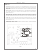
In order to properly align the SVR-200, you will need two service monitors and the mobile radio that the repeater
will be installed with. Refer to figure 2 for alignment points.
Dis-assemble the repeater by removing the two cap screws on the rear panel and the phillips screw on the
bottom. Slide the main circuit board out of the housing with the rear panel attached. Connect one service monitor
to the SVR-200 TNC jack and the other to the mobile antenna jack. Connect the cable from the mobile radio to
the SVR-200 (See figure 4 on page 14). Turn on the mobile and activate the SVR-200.
Adjust the repeater squelch control (RV9) so that the repeater COR led is off. Adjust the mobile so that the audio
is squelched.
SVR-200 UHF Transmitter
1. Transmitter Output: Short J3 and adjust RV10 for maximum. Confirm the SVR-200 RF Power out is at least
2W . Adjust RV10 for 250 mW. The SVR-200 case is integral to the voltage regulator heat sink and the unit
should not transmit at full power when removed from the case for extended periods.
2. Transmitter frequency: Adjust the TCXO on the RF board for the transmit frequency.
3. Maximum deviation/lock tone deviation: Adjust RV7 (lock tone deviation) for maximum. If the SVR-200
is programmed for sub-audible encode, adjust RV6 (CTCSS) for minimum. Adjust RV8 (repeater deviation)
for 95% deviation. Adjust RV7 for 60% deviation. Remove J3.
4. Mobile COR: Measure the voltage at TP2 on the SVR-200 main PCB and record. Set the mobile service
monitor for the mobile receive frequency, 1mV RF output and CTCSS modulation of 15%. Measure the voltage
again at TP2 and record. Turn the mobile service monitor off and adjust RV1 on the SVR-200 main board for
the halfway point between the two voltage readings as read at pin 3 of U1.
5. RX audio sensitivity/CTCSS deviation: Set the service monitor connected to the mobile for the mobile receive
frequency and 1mV RF output. Modulate the signal generator with a 1kHz tone at 60% deviation and CTCSS
tone at 15% deviation. Ensure that the SVR-200 mobile COR and repeater PTT LED’s are on. Adjust RV5
on the SVR-200 main board for 60% deviation as read on the service monitor connected to the SVR-200. If
programmed for sub-audible encode, remove the 1kHz tone deviation from the mobile service monitor and
adjust RV6 on the SVR-200 main board for 15% deviation. Turn the RF output from the mobile service monitor
off and ensure that the SVR-200 mobile COR and repeater PTT LEDs are off.
6. Local mic repeat: If the SVR-200 is programmed for local mic repeat, key the mobile local mic and inject an
audio signal into the local mic to produce 60% deviation on the service monitor connected to the mobile.
Confirm that the SVR-200 repeater PTT LED is on; adjust RV2 for 60% deviation as read on the service
monitor connected to the SVR-200. Unkey the mobile radio.
7. RF power out: Short J3 and adjust RV10 for the operating power output. Open J3.