Wireless Microphone System WM-1000 Product Manual
Forward Scope of this manual This manual contains the specifica ons, func onal descrip on, opera ng instruc ons, schema c, parts locator and parts list for the WM-1000 Wireless Microphone System. This manual is intended for use by qualified service technicians to aid them with installa on, interfacing, alignment and trouble shoo ng of the WM-1000 when used with other land mobile radios.
RF Exposure Statement The WM-1000 has been shown to be compliant for localized specific absorp on rate (SAR) for uncontrolled environment/general exposure limits specified in ANSI/IEEE Std. C95-1-1992 and had been tested in accordance with the measurement procedures specified in IEEE 1528-2013, OET Bulle n 65 Supp. C and EN/IEC 62209. To maintain compliance with RF exposure limits, a 20cm separa on distance must be maintained between the WB-1000 and any persons.
Industry Canada informaƟon IC ID: 2390A-WM1000, 2390A-WB1000 This device complies with Industry Canada licence-exempt RSS standard(s). Opera on is subject to the following two condi ons: (1) this device may not cause interference, and (2) this device must accept any interference, including interference that may cause undesired opera on of the device. Le présent appareil est conforme aux CNR d’Industrie Canada applicables aux appareils radio exempts de licence.
This radio transmi er 2390A-WM1000 & 2390A-WB1000 have been approved by Industry Canada to operate with the antenna types listed below with the maximum permissible gain and required antenna impedance for each antenna type indicated. Antenna types not included in this list, having a gain greater than the maximum gain indicated for that type, are strictly prohibited for use with this device.
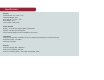
Specifications Physical Handheld Size: 4.3” x 2.6” x 1.5” Handheld Weight: 6 oz. Base Size 3.8 “ x 2.75” x 2.75” Base Weight: 5 oz. Construc on: ABS Plas c Power & Audio Ba ery: 3.7V Lithium Polymer Ba ery, 2000mAH Speaker: 1.6 Wa Internal Speaker External Audio Output: 3.5mm Headphone Connector TransmiƩer Frequency Range: 902 - 928 MHz, Frequency Hopping Spread Spectrum (Fixed Channel) RF Power Output: +13.
Functional Description The WM-1000 is a state of the art spread spectrum unlicensed radio system that provides extended coverage for mobile radio users. This portable radio system integrates with your exis ng mobile radio to give users handheld coverage when outside of their vehicle. With no license required, the WM-1000 offers ease of implementa on when compared to tradi onal SMR vehicular repeater systems.
The WM-1000 System can be configured to operate in one of two modes. First, the WM-1000 can be configured to be uniquely paired to the WB-1000 base in the vehicle. This provides private secure communica ons to your vehicle mounted mobile radio. If you work together with other users on a regular basis, the WM-1000 can be configured to work in group mode. This allows handheld users to communicate with each other on a common channel.
WM-1000 User Functions
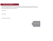
WB-1000 Installation Before installing the WB-1000, ensure that the mobile radio is properly aligned per the manufacturer’s tuning instruc ons. Addi onally, ensure that the WB-1000 jumper switches are properly configured for use with the parcular mobile radio that it will be connected to: SW2: RS-232 SW3: RS-485 SW4: Emergency Opera on Visit www.pyramidcomm.com for up to date installation guides on your specific mobile radio.
Proin iaculis lacus vitae Make the connec ons between the mobile radio and the WB-1000 cable as follows: ligula lacinia in fermenPin 1: Pin 2: Pin 3: Pin 4: Pin 5: Pin 6: tum ligula elementum. Etiam ut elit dui. Sed augue felis, hendrerit in interdum sit amet, mollis semper turpis. Pellentesque malesuada, leo vel volutpat tempus Ground. Connect to the radio’s chassis or ground plane. Mobile transmit audio. Connect to the mobile transmit audio path or tone input.
Pin 7: Mobile COR detect. This line is used to indicate when the SVR-P250 should repeat the transmission to the handheld. Connect to a logic point in the radio that indicates proper tone and carrier have been detected or the audio unmute line. If this line goes more posi ve during an unmute condi on, program the mobile COR line as ac ve high (common data). If the line goes more nega ve during an unmute condi on, program the mobile COR line as ac ve low.
Pin 9: On-Air detect. Trunking: Connect to a point in the radio that indicates the mobile transmi er is actually on the air. This is not the same as mic PTT. If pin 9 goes posi ve during transmit, program the on-air detect line for ac ve high (common data). If pin 9 goes to ground during transmit, program the on air detect line for ac ve low. Conven onal: Used for local mic repeat indica on from the mobile. Connect pin 9 to pin 4 of the SVR-P250 and program the on-air detect line for ac ve low.
37 Shield, 714-901-5462 Irvine, CA 92618 ww.pyramidcomm.