PLMR87WB OWNER’S MANUAL Mobile Audio System PLL Synthesizer Stereo Radio Automatic Memory Storing USB Interface SD Interface 3.5mm input jack Weather Band function www.PyleUSA.
CONTENTS Installation ........................................... 3 Take out screw before installation ......... 3 DIN Front-Mount ................................. 3 Installing the unit ............................... 3 Removing the unit ............................. 4 Wiring Connection .............................. 5 Operation ............................................. 6 Location of keys .................................... 6 Switching on/off the unit ........................ 7 Sound adjustment ......
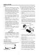
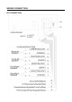
INSTALLATION Notes: Choose the mounting location where the unit will not interfere with the normal driving function of the driver. Before finally installing the unit, connect the wiring temporarily and make sure it is all connected up properly and the unit and the system work properly. Use only the parts included with the unit to ensure proper installation. The use of unauthorized parts can cause malfunctions.
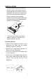
INSTALLATION Screw (5x25mm) and Plain Washer) to attach the other end of metal strap to a solid metal part of the vehicle under the dashboard. This strap also helps ensure proper electrical grounding of the unit. Note to install the short threading terminal of the mounting bolt to the back of the unit and the other long threading terminal to the dashboard. Spring Washer Hex Nut Metal Strap Mounting Bolt Plain Washer Tapping Screw 7. Reconnect the cable to the vehicle battery’s negative (-) terminal.
WIRING CONNECTION ISO CONNECTION 5
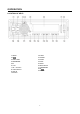
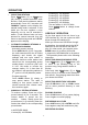
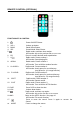
OOPERATION LOCATION OF KEYS 1.AS/PS 2.9/ 3.PUSH /SEL 4.PWR/MODE 5.IR 6. LCD 7.SD interface 8. USB interface 9.AUX IN 10.6 DIR+ 11.5 DIR12.4 RDM 13.3 RPT 14.2 INT 15.1PAU 16.Reset button 17.7/BAND/WB 18.8/ 19.
OPERATION DISP button the “MM” will flash. Press the / to change the minute. Then press DISP button to confirm. SWITCHING ON/OFF THE UNIT Press PWR button (4) to turn on the unit. When the unit is on. Press and hold for 2 seconds to turn off the unit. LIQUID CRYSTAL DISPLAY Exhibit current frequency and activated functions on the display . SOUND ADJUSTMENT Press SEL button (3) shortly to select the desired adjustment mode.
OPERATION 2 button(21): 162.400MHz 3 button(22): 162.475MHz 4 button(23): 162.425MHz 5 button(24): 162.450MHz 6 button(25): 162.500MHz The next station is 162.525 MHz. Press / button to change these stations. SELECTING STATION Press 9/ button (2) or 8/ button (18) shortly to activate automatic seek function. It will search up/down a station automatically. Press for 2 seconds until “MANUAL” appears on the display, the manual tuning mode is selected.
OPERATION CAUTION: When there are important files in the USB Device or SD card, do not connect it to the main unit to play, because any wrong operation may cause files loss. And our company assumes no responsibility for this. Press 3 RPT button (13) to continuously repeat the same file. Press it again to repeat all files. PLAYING IN RANDOM ORDER Shortly press 4 RDM button (12) to play all files in random order. Press it again to cancel the function.
REMOTE CONTROL (OPTIONAL) FUNCTION KEY & CONTROL 1. Power ON/OFF Button. 2. 3. 4. 5. VOL+ BAND SEL 6. 7. EQ 1/ 8. 4/RDM 9. 6/+10/DIR+: 10. 5/-10/DIR-: 11. 3/RPT 12. 2/INT 13. DISP 14. VOL15. 16.AMS 17. 18. MODE Volume up button. Band Select Button. Sound Mode Select Button Radio mode: seek/turn down station. MP3 mode: skip to the previous file or fast reverse. Press it to select desired audio equalization. Radio mode: Preset number 1. MP3 mode: Pause/playing file.
SPECIFICATION GENERAL Power Supply Requirements Chassis Dimensions Tone Controls - Bass (at 100 Hz) - Treble (at 10 kHz) Maximum Output Power Current Drain : DC 12 Volts, Negative Ground : 178 (W) x 97 (D) x 50 (H) : ±10 dB : ±10 dB : 4x50 watts : 10Ampere (max.) RADIO Frequency Coverage IF Sensitivity (S/N=30dB) Stereo Separation FM 87.5 to 107.9 MHz. 10.
TROUBLE SHOOTING Before going through the checklist, check wiring connection. If any of the problems persist after checklist has been made, consult your nearest service dealer. Symptom Cause Solution The car ignition switch is not on. If the power supply is connected to the car accessory circuits, but the engine is not moving, switch the ignition key to “ACC”. The fuse is blown. Replace the fuse. Volume is in minimum Adjust volume to a desired level. Wiring is connected. Check wiring connection.