
User Manual

- 4 -
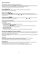
- Only use speakers with 4 ohms impedance.
- Do not attach the control panel to the chassis before wiring is complete.
- The maximum current of the auto antenna is 200mA.
Wiring Connections
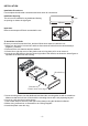
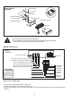
Removal of the Main Unit
1. Remove the metal strap from the main unit.
2. Remove the plastic trim out from the main unit.
3. Insert a bracket key into the left and right side of the main unit and draw the unit out of the mounting
sleeve.
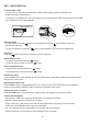
INSTALLATION
DIAGRAM
SPRING WASHER
PLAIN WASHER
TAPPING SCREW
HEX NUT
HEX NUT
DASH BOARD
CONSOLE
MOUNTING SLEEVE
HEX BOLT
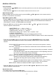
ACC + (Red)
GND - (Black)
ANT + (Blue)
Power B+ (Yellow)
Green
Purple
Rear Right
Speaker
Front Right
Speaker
Rear Left
Speaker
Front Left
Speaker
Purple/Black
Green/Black
White
White/Black
Gray
Gray/Black
15A
WIRING
DIAGRAM
Radio Antenna Socket
White: Left CH Auxiliary RCA Audio Input
Red: Right CH Auxiliary RCA Audio Input
White: Front Left CH RCA Audio Output
Red: Front Right CH RCA Audio Output
White: Rear Left CH RCA Audio Output
Red: Rear Right CH RCA Audio Output
FUSE 15A
CAUTION
+12V DC
NEGATIVE
GROUND