Invincible Series Amplifier
INTRODUCTION PYLE amplifiers provides high-performance sound reinforcement for your mobile audio equipment. Its versatility enables compatibility with optional Equalizers, Frequency Dividing Crossover Networks, and other audio processors in customized system. The Multi-Mode bridging capabilities allow flexibility in hosting several different speaker configurations. To achieve optimum performance, it is highly recommended that you read this Owners Manual before beginning installation.
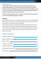
PLANNING YOUR SYSTEM Before beginning the installation, consider the following 1. Do you plan to add additional mobile electronics equipment in the future? If you plan to expand your system by adding other components sometime in the future, ensure adequate space is left, and cooling requirements are met. 2. Should you use high or low level inputs? Your Amplifier has been designed to accept Low-Level (Pre-Amp outputs from your radio) signal source.
1. Ground: To Vehicle Chassis To avoid unwanted ignition noise caused by ground loop, it is essential that the Amplifier be grounded to a clean, bare, metal surface of the vehicle's Chassis. NOTE: GROUND WIRE SHOULD NOT BE EXTENDED MORE THAN 3 FT, (1 METER). 2. +12 Volt (Fused) Constant Power: To Battery (+) Due to the power requirements of the Amplifier, this connection should be made directly to the positive (+) terminal of battery.
PANEL LAYOUT INV139A/INV159A FRONT VIEW INV239A/INV259A FRONT VIEW INV449A FRONT VIEW www.PyleUSA.
INV139A/INV159A REAR VIEW INV239A/INV259A REAR VIEW INV449BA REAR VIEW 6 www.PyleUSA.
TOP VIEW INV139A/INV239A TOP VIEW INV159A/INV259A TOP VIEW INV449A TOP VIEW www.PyleUSA.
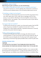
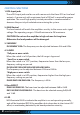
CONTROL FUNCTIONS 1. RCA Input jacks These RCA input jacks are for use with source units that have RCA or Line level outputs. A source unit with a minimum level of 200mV is required for proper operation. The use of high quality twisted pair cables is recommended to decrease the passivity of radiated noise entering the system. 2. GAIN Control The level control will match the amplifiers senstity to the source units signal voltage. The operating range is 200mW minimum to 6W maximum.
7. Auxiliary Outputs The Auxiliary outputs offer PYLE amplifiers easy, unlimited system expansion. Route RCA, from the line out of the first amplifier to the line input of a second amplifier when using a single source output. 8. GND Connect this terminal directly to the sheet metal chassis of the vehicle using the shortest wire necessary to make this connection. Always use wire of the same gauge or larger than the (+) 12 volt power wire. The chassis connection point should be scraped free of paint and dirt.
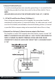
SPEAKER CONNECTION MONO Channel System Design #1 INV139/INV159A 10 www.PyleUSA.
2 Channel System Design #1 INV239A/INV259A www.PyleUSA.
2 Channel System Design #2 INV239A/259A 12 www.PyleUSA.
2 Channel System Design #3 INV239A/259A www.PyleUSA.
4 Channel System Design #1 INV449A 14 www.PyleUSA.
4 Channel System Design #2 INV449A www.PyleUSA.
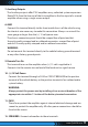
TROUBLESHOOTING GUIDE Issue NO SOUND UNIT WILL NOT TURN ON Possible Cause Solution Check all fuses, replace if necessary. Is the power LED Make sure the power is securely illuminated? fastened.
20K INPUT IMPEDANCE (LOW LEVEL) PRODUCT DIMENSIONS (L x W x H) 0-80Hz 50-250Hz 80Hz 45KHz 0.01 1CHx1000W 2CHx350W 0-80Hz 50-250Hz 80Hz 45KHz 0.01 1CHx2000W 2CHx650W 2CHx500W 2000W INV259A NONE 50-250Hz 80Hz 45KHz 0.01 2CHx1000W 4CHx350W 4CHx250W 2000W INV449A 40Ax1 20K 0.2-6V 25Ax1 20K 0.2-6V 40Ax1 20K 0.2-6V 25Ax2 20K 0.2-6V 9.21'' x 8.13'' x 2.28'' -in 12.36'' x 8.13'' x 2.28'' -in 9.21'' x 8.13'' x 2.28'' -in 12.36'' x 8.13'' x 2.28'' -in 14.33'' x 8.13'' x 2.
Questions? Comments? We are here to help! Phone: (1) 718-535-1800 Email: support@pyleusa.