PLCD67 OWNER’S MANUAL Mobile Audio System • PLL Synthesizer Stereo Radio • Digital Compact Disc Player • Automatically Memory Storing • Preset Equalization • Remote Control • Electronic Detachable Panel
CONTENTS Installation .....................................................................................................3 DIN Front-Mount (Method A) ..................................................................................3 Installing the unit ...............................................................................................3 Removing the unit .............................................................................................4 DIN Rear-Mount (Method B) ....................
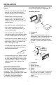
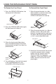
INSTALLATION Notes: DIN FRONT-MOUNT (Method A) • Choose the mounting location where the unit will not interfere with the normal driving function of the driver. Installing the unit 1 2 • Before finally installing the unit, connect the wiring temporarily and make sure it is all connected up properly and the unit and the system work properly. 182 53 3 • Use only the parts included with the unit to ensure proper installation. The use of unauthorized parts can cause malfunctions. (Fig. 1) 1.
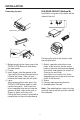
INSTALLATION Removing the unit DIN REAR-MOUNT (Method B) Installation using the screw holes on the sides of the unit. 1 1 2 Open/Close 4 2 2 3 3 4 Fastening the unit to the factory radio mounting bracket. 1. Before removing the frame, press the OPEN/CLOSE button to slide down the front panel. 2. Frame 3. Insert fingers into the groove in the right side of the frame and pull out to remove the frame. (You can also remove the frame from the left side.) 4.
USING THE DETACHABLE FRONT PANEL To Detach the Front Panel To Reinstall the Front Panel 1. Press the OPEN/CLOSE button, the front panel will slide down. 1. When the panel bracket is in slide down position, insert the front panel into panel bracket and press OPEN/CLOSE button to slide up. Open/Close 2. Press the OPEN/CLOSE button again, the front panel will slide up. Bottom Button 2.
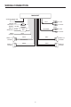
WIRING CONNECTION MAIN UNIT ANTENNA CONNECTOR (BLACK) Rch RED CD IN IGNITION RED SWITCH (B+) MEMORY YELLOW BACK-UP BLACK GROUND (B–) Lch WHITE (GREY) CHOKE BOX RCA CABLE Rch RED Lch WHITE POWER ANTENNA FRONT Lch SPEAKER REAR Lch SPEAKER BLUE WHITE GREY WHITE/BLACK GREY/BLACK GREEN VIOLET GREEN/BLACK VIOLET/BLACK 6 FRONT Rch SPEAKER REAR Rch SPEAKER
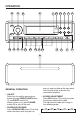
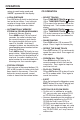
OPERATION 10 13 11 24 16 12 17 19 8 20 2 23 15 21 14 22 18 6 1 7 9 4 3 5 press it again to slide up the front panel into the main body or detach the removable faceplate. GENERAL OPERATION • ON/OFF Switch on the unit by pressing any button (except OPEN/CLOSE button (7) and EJECT button (4)). When system is on, press POWER button (9) to turn off the unit. • SOUND ADJUSTMENT Press SEL button (10) shortly to select the desired adjustment mode.
OPERATION For Electrical Volume: By pressing AUDIO CONTROL button (11) or AUDIO CONTROL button (12), it is possible to adjust the desired sound quality. For Digital Rotating Volume: By rotating the knob (11 & 12) clockwise or counter-clockwise, it is possible to adjust the desired sound quality. • REMOTE SENSOR Point the remote control handset to the remote sensor RX (23). Press the function keys on the handset to control the system.
OPERATION retune to seek tuning mode and “AUTO” appeared on the display. CD OPERATION • SELECT TRACKS Press TUNE/SKIP/TRACK button (16) or TUNE/SKIP/TRACK button (17) to move to the previous track or the following track. Track number shows on display. Hold TUNE/SKIP/TRACK button (16) or TUNE/SKIP/TRACK button (17) to fast reverse or fast forward. CD play starts from when you release the button. • LOCAL/DISTANCE Press LOC button (3) shortly to select between local and distant stations.
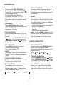
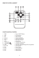
REMOTE CONTROL HANDSET 1 7 4 3 8 9 6 5 13 2 12 10 11 14 15 FUNCTION KEYS & CONTROL 1. 2. 3. 4. 5. 6. 7. 8. 9. 10. 11. 12. 13. 14. 15.
SPECIFICATION GENERAL Power Supply Requirements Chassis Dimensions Tone Controls - Bass (at 100 Hz) - Treble (at 10 KHz) Maximum Output Power Current Drain : DC 12 Volts, Negative Ground : 178 (W) x 180 (D) x 50 (H) : : : : ± 10 dB ± 10 dB 4 x 50 Watts 5 Ampere (max.) CD PLAYER Signal to Noise Ratio Channel Separation Frequency Response : More than 55 dB : More than 50 dB : 20 Hz - 20 KHz RADIO FM 87.5 to 107.9 MHz 10.
TROUBLE SHOOTING Before going through the check list, check wiring connection. If any of the problems persist after check list has been made, consult your nearest service dealer. Symptom No power. Disc cannot be loaded or ejected. No sound. Sound skips. The operation keys do not work. Cause Solution The car ignition switch is not on. If the power supply is properly connected to the car accessory circuits, but the engine is not moving, switch the ignition key to “ACC”. The fuse is blown.