PLCD29 OWNER’S MANUAL Mobile Audio System • PLL Synthesizer Stereo Radio • Digital Compact Disc Player • Automatically Memory Storing • Full Detachable Panel • Auxiliary Input Function
CONTENTS Installation ............................................................................................... 3 DIN Front-Mount (Method A) ........................................................................... 3 Installing the unit ........................................................................................ 3 Removing the unit ...................................................................................... 4 DIN Rear-Mount (Method B) .....................................
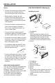
INSTALLATION Notes: DIN FRONT-MOUNT (Method A) • Choose the mounting location where the unit will not interfere with the normal driving function of the driver. Installing the unit 1 2 • Before finally installing the unit, connect the wiring temporarily and make sure it is all connected up properly and the unit and the system work properly. 182 53 3 • Use only the parts included with the unit to ensure proper installation. The use of unauthorized parts can cause malfunctions. (Fig. 1) 1.
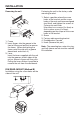
INSTALLATION Removing the unit Fastening the unit to the factory radio mounting bracket. 1 1. Select a position where the screw holes of the bracket and the screw holes of the main unit become aligned (are fitted), and tighten the screws at 2 places on each side. Use either truss screws (5 x 6mm) or flush surface screw (4 x 6mm), depending on the shape of the screw holes in the bracket. 2. Screw 3. Factory radio mounting bracket 4. Dashboard or Console 5. Hook (Remove this part) 2 3 1. Frame 2.
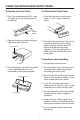
USING THE DETACHABLE FRONT PANEL To Detach the Front Panel To Reinstall the Front Panel 1. Press the release button (REL), then the right-hand side of the panel will be ejected. 1. Push the front panel into the main body. A ‘click’ sound should be heard. Release Button 2. Remove the front panel by pulling its right-hand side outward. 2. Note that if the front panel fails to lock in position properly, press control button may not function and LCD display may be missing some segments.
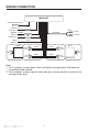
WIRING CONNECTION MAIN UNIT ANTENNA CONNECTOR IGNITION RED SWITCH (B+) MEMORY YELLOW BACK-UP BLACK GROUND (B–) POWER ANTENNA 2-SPEAKERS SYSTEM WHITE FUSE (GREY) RCA CABLE CHOKE BOX Rch RED Lch WHITE BLUE 4-SPEAKERS SYSTEM 4-SPEAKERS SYSTEM FRONT Lch SPK. WHITE GREY WHITE/BLACK GREY/BLACK 2-SPEAKERS SYSTEM GREY FRONT Rch SPK. Lch SPK. Rch SPK. GREEN/BLACK REAR Lch SPK. GREEN VIOLET GREEN/BLACK VIOLET/BLACK REAR Rch SPK. VIOLET/BLACK Note: 1.
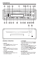
OPERATION 4 6 3 1 7 9 14 11 10 2 12 23 20 15 16 18 22 8 5 21 19 13 17 24 25 26 • LOUDNESS Press LOU button (6) to increase bass output and display will show “LOUD”. GENERAL OPERATION • ON/OFF Press the PWR button (1) to turn on. Press PWR again to turn it off. • SET THE CLOCK Press and hold the DSP button (7), the clock will show on the display, then press the TRACK/TUNE button (16) to change minutes or TRACK/TUNE button (15) to change hours.
OPERATION Use VOLUME (10) and VOLUME (11) buttons to adjust the selected mode. When mode has not been adjusted for several seconds, display returns to normal radio or CD display. BA (Bass) TR (Treble) B (Balance) F (Fader) RADIO OPERATION • SELECT BAND Press BAND button (12) to change between three FM bands and two AM bands. Each band stores up to six preset stations. V(Volume) FM1 • SELECT LISTENING MODE Press MOD button (13) to choose desired listening mode. (e.g.
OPERATION Preset Scanning Press AMS button (18) shortly to toggle preset scanning function. During the scanning, it will stop at every stored station for several seconds and the frequency of station being scanned flashes on the display. Press it again to stop scanning. CD OPERATION • DISC PLAY Push a compact disc with the label side facing up into the disc slot (2). When there have correspondingly showing on the display, press button (19) to start playing with the first track of the disc.
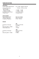
SPECIFICATION GENERAL Power Supply Requirements Chassis Dimensions Tone Controls - Bass (at 100 Hz) - Treble (at 10 KHz) Maximum Output Power Current Drain : DC 12 Volts, Negative Ground : 178 (W) x 155 (D) x 50 (H) : : : : + 10 dB / – 10 dB + 10 dB / – 10 dB 4 x 40 Watts (max.) 5 Ampere (max.) CD PLAYER Signal to Noise Ratio Channel Separation Frequency Response : More than 60 dB : More than 60 dB : 20 Hz - 20 KHz RADIO FM 87.5 to 107.9 MHz 10.
TROUBLE SHOOTING Before going through the check list, check wiring connection. If any of the problems persist after check list has been made, consult your nearest service dealer. Symptom No power. Disc cannot be loaded or ejected. No sound. Sound skips. The operation keys do not work. Cause Solution The car ignition switch is not on. If the power supply is properly connected to the car accessory circuits, but the engine is not moving, switch the ignition key to “ACC”. The fuse is blown.
www.pyleaudio.