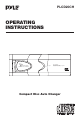
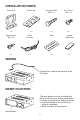
PLCD20CH OPERATING INSTRUCTIONS 10 DIGITAL AUDIO COMPACT DISC CHANGER Open Disc Magazine Compact Disc Changer System Disc Auto Changer Compact Disc Auto Changer
CONTENTS HINTS FOR CORRECT AND SAFE OPERATION HOW TO USE THE MAGAZINE PRECAUTIONS FOR HANDLING DISCS INSTALLATION PARTS WIRING RESET FUNCTION BEFORE INSTALLING THE UNIT • Transport Lock Screws • Installation and Wiring Precautions • Position of the built-in anti-vibration Board INSTALLATION • Procedure for Installation on Carpet (Horizontal Position) • Procedure for Installation on Carpet (Vertical Position) • Procedure for Installation on Carpet (At a 45° angle) • Procedure for Installation (Suspended Posi
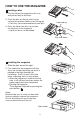
HOW TO USE THE MAGAZINE Loading a disc 1. Pick the tab on the magazine’s disc tray and pull out only of the trays. 2. Place the disc on the tray with its play surface facing down (label surface facing up). • Each tray can accommodate only one disc. Label side up 3. Press the tab on the disc tray to store the tray back in the magazine. • Up to ten discs can be loaded. Play side down Installing the magazine 1. Slide the door toward the right. 2.
PRECAUTIONS FOR HANDLING DISCS With new discs The symptoms described below sometimes occur when new discs are used: • The disc is not played even when it is loaded. • Operation changes to the next disc before the first disc has a chance to be played. • The same disc is played over and over again. • The designated disc is not played. Burrs Burrs Center hole Outside circmference Remove all plastic particles of burr from surfaces of disc before loading in magazine.
INSTALLATION PARTS Bracket (A) Bracket (B) Hexagonal Bolt (M6 x 12) Truss Screw (M4 x 5) x2 x2 x4 x4 Tapping Screw (M5 x 12) DIN 8 Pin Cable Seal Double Sided Tape x4 x1 x1 x2 WIRING Connect this cable to the terminal of the CD player. RESET FUNCTION The reset button must be activated with either a ball point pen or thin metal object. It is to be activated for the following reason: • Initial installation of the unit when all wiring is completed. • Some functions do not operate.
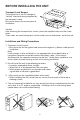
BEFORE INSTALLING THE UNIT Transport Lock Screws The mechanism in the CD changer is “locked” into place during shipment by the transport screws. Be sure to remove the screws prior to installation. Caution After removing the transport lock screws, place the supplied seals over the screw holes. These seals are used to keep dust, which could cause a malfunction, out of the unit. Installation and Wiring Precautions 1. To prevent a short-circuit.
Position of the built-in anti-vibration board This unit can be installed horizontally (suspended), vertically, and at a 45° angle. Once the installation position has been decided, it’s necessary to set the position of the built-in anti-vibration board inside the unit. Please do this before performing the procedure listed below. Vibration may cause the disc to skip if the unit is used before properly setting the anti-vibration board.
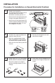
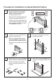
INSTALLATION Procedure for Installation on Carpet (Horizontal Position) 1 • Confirm that the built-in anti-vibration boards on both the left and right sides are set to the horizontal installation position “0”. Built-in anti-vibration board position Hexagon bolts (M6 x 12) • Attach the left and right brackets (A) using the hexagonal bolt (M4 x 5). • Attach the left and right brackets (A) to their respective brackets (B) using the hexagonal bolts (M6 x 12) and the hexagonal nuts (M6).
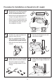
INSTALLATION Procedure for Installation on Carpet (Vertical Position) 1 • Set that the built-in anti-vibration boards on both the left and right sides are set to the vertical installation position “90”. Built-in anti-vibration board position Hexagon bolts (M6 x 12) • Attach the left and right brackets (A) using the hexagonal bolt (M4 x 5). • Attach the left and right brackets (A) to their respective brackets (B) using the hexagonal bolts (M6 x 12) and the hexagonal nuts (M6).
INSTALLATION Procedure for Installation on Carpet (at a 45° angle) 1 • Set the built-in anti-vibration boards on both the left and right sides to the 45° installation position “45°”. Built-in anti-vibration board position • Attach the left and right brackets (A) using the hexagonal bolt (M4 x 5). Hexagon bolts (M6 x 12) • Attach the left and right brackets (A) to their respective brackets (B) using the hexagonal bolts (M6 x 12) and the hexagonal nuts (M6).
INSTALLATION Procedure for Installation (Suspended Position) 1 • Confirm that the built-in anti-vibration boards on both the left and right sides are set to the horizontal installation position “0”. Built-in anti-vibration board position • Attach the left and right brackets (A) using the hexagonal bolt (M4 x 5). Hexagonal Bolts Hexagonal Bolts 2 3 • Determine the mounting location and drill four mounting holes. 3.6ø 11 • Attach the CD changer with the tapping screws (M5 x 12).
HANDLING THE DISCS Dirt, dust, scratches and warpage cause sound skips during playback and a deterioration of sound quality. How to take care of your disc: 1. Use compact discs that have the mark shown on the right. 2. Fingerprints and dust should be carefully wiped off the disc’s signal surface (glossy side) with a soft cloth. Unlike conventional records, the compact disc has no grooves to collect dust and microscopic debris, so gently wipe with a soft cloth should remove most particles.
OPERATING INSTRUCTIONS SELECT RESET SCAN REPEAT RANDOM DISC OFF TRK/SKIP CD Changer Remote Control System 13
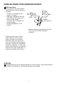
PARTS AND THEIR FUNCTIONS Control section 1 3 2 4 SELECT SCAN REPEAT RANDOM 5 6 7 DISC RESET 8 9 OFF TRK/SKIP Liquid Crystal Display (LCD) - (1) LCD display will only be active when the changer power is on. This display indicates all operation key’s, including DISC number, track number. Select Button (2) Press this button to select functions. Functions are shown below: OFF REPEAT ONE REPEAT ALL SCAN ONE RANDOM ONE Scan Play Button (Track Scan) - (3) Upon pressing this button.
Random Play Button (Track or DISC Random) - (5) This is used for random selection Disc play, and sequence. Once this button is pressed. “RANDOM ONE” is displayed in the Upper left corner of LCD commander, and disc selection will begin random play. Press this button for a second, “RANDOM ALL” will be shown on the display. When “RANDOM ALL” function is activated, all tracks of each CD will be played in random order until all of them have been played once.
Reset Button A reset button is located on the front panel of the unit which must be activated with a pen tip or other thin object as it is recessed to prevent accidental engagement. 1. Initial installation after all wiring is completed. 2. If abnormal disc operation is encountered, the reset button may be pressed to clear the system and return to normal operation.
BEFORE USING THE SYSTEM SETTING UP FOR OPERATION Be sure to press reset button when all wiring is completed. Load the discs into the CD magazine and install the magazine into the CD changer. Wiring — Using FM Modulator This system is designed to convert CD sound into FM signals (89.1 MHz or 88.7 MHz) and play them on the existing FM car stereo. Carry out the steps outlined below before using the system. Turn on the car stereo and select FM band operation. Tune the radio to either 89.1 or 88.
CD CHANGER OPERATION Listening to the CD Play • Playing a CD Press the play/pause button (.......). Adjust the volume and tone using the FM car stereo to which the system is connected. * When using the system for the first time or when the CD magazine has just been replaced, play starts from the first track on the first disc. • To temporarily stop CD play Press the play/pause button (.......) during play. Disc number flashes on the display and play is temporarily stopped.
• Random play - When the random button (RANDOM) is pressed, “RANDOM ONE” appears, and the tracks on the disc now heard are played in a random order. When all the tracks have been played, they will be played again, this time in a different random order. - Press this button for a second, “RANDOM ALL” will be shown on the display. When “RANDOM ALL” function is activated, all tracks of each CD will be played in random order until all of them have been played once.
Wiring — FM Modulator unit To car antenna FM Modulator Fuse 0.5A RF output (89.1MHz or 88.7 MHz) Fuse 5A Antenna socket To + 12V ACC. Speaker ACC/Ignition power lead (red) Connect to where the power is supplied when the ACC power or ignition switch is turned ON. Battery power lead (pink) Memory back up. To be connected to continuous power source. Ground lead (black) Screw this to a metal part of the vehicle. DIN connection cord (6-pin) Commander SELECT RESET FM Radio CD Changer Interference on 89.
Control and Function Keys 1 2 3 4 0.5A RED K PIN CK A BL CK A BL CK A BL 5A 5 6 7 1. +12V TO IGNITION Connect the red power wire (with in-line fuse holder) to a point in your vehicle’s fuse block that has power only when you turn the vehicle’s key to either the accessory (ACC) or START position. 2. ANTENNA If your system does not have an RCA input jack, use the FM Modulator to covert CD Changer’s sound to FM signal. You can then hear it by tuning your vehicle system to FM frequency.
4. OUTPUT FREQUENCY Turn the switch on the side of the FM Modulator to choose the output frequency between 89.1 MHz and 88.7 MHz with a screwdriver. When the reception is interfered with other station on the one frequency, switch to the another frequency. 5. RESET (FOR MODULATOR FUNCTION ONLY) If the CD Changer locks up or does not work properly, press the reset button with a pointed object. 6.
TROUBLESHOOTING An error made in operation or in the connections is sometimes mistaken for a failure or breakdown. Perform the checks described in the following table before calling in the servicing engineer. Symptom Cause Remedy No power. Improper connection. Check connections. Magazine cannot be installed. Direction in which it is inserted is wrong. Insert it in proper direction. CD is not played. Disc has been loaded upside down. Load disc with play side facing up.
88-D0040-14