
Printer User Manual


Part 9
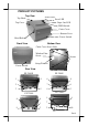
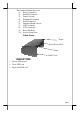
Install Cable Cover
Check the bottom view of the printer, the 4
screws for the printer itself are in quite deep holes. Insert
the tenons of the cable cover into the 2 printer screw
holes nearest to the connection area. Apply a cable cover
fixing screw at the matched screw holes as circled in the
bottom view picture at right.
Power On
When all the above cable connections are made
correctly, you may connect your power adaptor to the
wall outlet. Make sure that the type of power cord and
the voltage requirement of the power adaptor meet the local power conditions.
Now the printer is ready for power on.
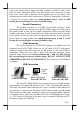
Self Test
Press and hold down the feed
button while turning the on / off switch on.
The printer will then perform a self-test. A
sample slip of self-test result is printed as in
the sample at right. Please note that both
serial and parallel interfaces are indicated.
That means the printer is working on an
auto-sensing and auto-select algorithm.
The header is printed in text mode
and the rest part of this slip is printed in
page mode. If FEED button is pressed at
this moment, a font table will be printed in
text mode again. To exit the test printing,
please turn the printer off and on again.
SPECIAL ADJUSTMENTS
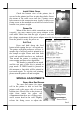
Paper Near End Sensor
The near end sensor for paper
roll in the printer is able to have the
printer work with paper rolls of several
bobbin sizes. Please refer to the picture at
right from inside the paper roll
compartment that there are a fixing screw
and a sensor head in the wall. Slightly
release the fixing screw to adjust the
Fixing Screw
Sensor Head