
Printer User Manual


Part 5
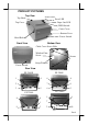
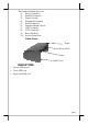
The numbered items above are:
1). Power Connector
2). Parallel Connector
3). Frame Ground
4). Peripheral Connector
5). Serial Connector
6). Interface Bracket Screw
7). USB Connector
8). LAN Connector
9). Reset Pin Hole
10). Service Serial Port
Cable Cover
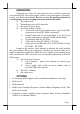
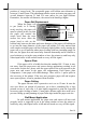
INDICATORS
• Power LED: green
• Error LED: red
• Paper Out LED: red
Tenon
Tenon
Screw Hole
Cable Cover