
Troubleshooting guide


PV500-23 04-2005 Section 23
5
POWER VT
®
BOILER
VENTING INSTRUCTIONS
VENT SIZING
Venting to and from this unit should conform to
the National Fuel Gas Code, Latest Edition. The
POWER VT
®
boiler is designed for operation with
the 4", 5” or 6” positive pressure vent systems
constructed of AL29-4C stainless steel.
WARNING: Do not use Type B vent or
plastic vent of any type. These materials
are not temperature or pressure rated
for this appliance and could result in
fire, injury, or death.
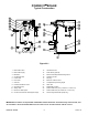
VENT SYSTEM DESIGN
The POWER VT
®
boiler can be vented either
vertically, through a ceiling or roof, or horizontally
through a wall. From the vent pipe at the blower
outlet, the vent can be routed in any direction
except down. Like any closed piping system, the
vent should maintain a downward slope toward
the heater of at least ¼ inch per lineal foot of
horizontal vent run to allow proper drainage of any
accumulated moisture. Despite this flexibility, the
following limitations and precautions must be
observed. (Per NFPA Z22.1-1 “Provision shall be
made to drain off and dispose of condensate from
a venting system.” A fitting, no more than 18” from
the combustion blower, should be provided in the
venting to route vent condensate away from the
blower.)
Determination of Equivalent Length
Maximum equivalent length of vent must not
exceed the length identified in Table 23-1:
Equivalent length Maximum Vent Length Vent Pipe
90° elbow 45° elbow 28 hp All others
4 14 5 50 100
5 18 7 150 300
6 21 8 390 500
Table 23-1
A. Add the total length of straight pipe (in feet).
B. Multiply the number of 90° elbows used in
vent system by the equivalent length of
straight pipe specified in Table 23-1.
C. Multiply the number of 45° elbows used in
vent system by the equivalent length of
straight pipe specified in Table 23-1.
D. Add (A), (B) and (C) together to obtain the
total feet of venting. This length must not
exceed the maximum vent length identified in
Table 23-1.
Example: A 4" venting system of 25 ft. of straight
pipe and two 90° elbows.
• Total straight pipe = 20 feet.
• Number of elbows (2) x 14 = 28 equivalent
feet of straight pipe.
• 20 feet plus 28 feet = 48 equivalent feet of
venting.
This is an acceptable vent system.
NOTE: Consult the vent system
manufacturer for specific design and
installation details.
Horizontal Venting Through a Wall
The vent must extend one foot beyond the wall.
The vent must not exit over a public walkway or
over any other area where condensate or vapor
could be hazardous.
The vent must discharge at least three feet above
grade of the level of normal snow accumulation.
The vent must terminate at least four feet below,
four feet horizontally from, or one foot above any
building air inlet including doors and windows.
Vertical Venting Through a Roof
• The vent must extend upwards beyond nearby
obstructions in accordance with Figures 23-2
and 23-3 (see page 7).
Venting of Multiple Units
• Multiple POWER VT
®
models must not be
vented into a common duct or breeching. Each
unit must be independently vented in
accordance with the instructions for either
horizontal or vertical venting included above.