
Troubleshooting guide


PV500-23 04-2005 Section 23
13
POWER VT
®
BOILER
GAS BURNER START-UP (con't)
While firing, check the gas pressure at the inlet of
the gas train. The minimum supply pressure
requirement on the Power VT boiler is 4.5" W.C.
supply unless otherwise specified on the data
plate. It should be a minimum of that shown
above with the boiler running at high fire. This is
recorded as inlet flow pressure. It is important
incoming pressure does not fall below this
minimum or nuisance control lockouts could
occur.
This section is for two-stage firing only: After
adjusting the high fire manifold gas pressure, it is
now important to check the operation of the first
stage (low fire). There is a toggle switch on the
control cabinet labeled “Auto/Low Fire”. Switch
from the auto position to low fire and the main
valve will de-energize shutting off the high fire gas
supply and the air damper will close reducing the
airflow to a minimum. Once the boiler is at low fire
the manifold gas pressure can be adjusted as
described in the previous paragraph but using the
pilot gas regulator instead of the main gas
regulator. Proceed to paragraph 10 to test and
document combustion results for low fire and high
fire.
10. Check flue gases with an electronic flue analyzer
to make final settings of gas pressure regulator.
a) The readings need to be taken from a hole in
the vent several inches downstream of the fan
outlet connection.
b) Insert 0-6" W.C. manometer into the test
opening in the vent. Pressure in stack should
not exceed 2" W.C.
c) When water in tank is above 120°F, insert
analyzer or O
2
testing in test opening; take O
2
reading in percentage.
d) Increase manifold gas pressure at the main
gas pressure regulator taking O
2
reading at
each adjustment of gas regulator until
optimum O
2
% (5-7%) is reached. If O
2
%
decreases, reduce the gas pressure to last
reading where the greatest reading is
achieved.
e) CO should not exceed 200 ppm. A reading
greater than 200 ppm indicates lack of air.
Reduce manifold gas pressure slightly and
take readings until CO is within proper range.
Optimum reading is no CO.
f) If manifold pressure was changed during
startup, take a final CO and O
2
reading.
g) Record CO
2
and
NO
x
if applicable. See
paragraph 11 if NO
x
measurement is required.
h) Insert vent temperature gauge in test opening
and read gross vent temperature; maximum
gross stack is to be 275°F. If an excessively
high gross vent temperature is recorded;
consult the factory.
11. When the Power VT Boiler is equipped for Low
NO
x
operation, it may be necessary to measure
the NO
x
levels in the flue products for
compliance verification. The NO
x
concentrations
are measured in ppm (parts per million). When
documenting the measurements on the startup
report, be sure to note whether or not the
readings are corrected to a baseline O
2
level. If
during the course of startup the NO
x
levels do
not meet your locally mandated requirements, it
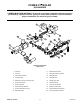
may be necessary to change the FGR (flue gas
re-circulation) orifice. This orifice is contained in
the FGR union shown on page 10, Figure 23-6.
This union may contain two or more orifices.
This allows the removal of one or more of the
orifices in order to increase the flow of FGR and
thereby reduce NO
x
in the flue products. If the
FGR orifice is changed for any reason, the
startup procedure in paragraph 10 should be
repeated.
12. Check each operating and limit control to be
sure they function properly by lowering and
raising the temperature setting on each of the
controls, causing burner to cycle on and off.
NOTE: During the initial firing of the burner,
smoke that is not related to the burner will be
emitted from the heater. This is normal during
"burn in" and could possibly continue for
several hours.