
Troubleshooting guide


PV500-23 04-2005 Section 23
10
POWER VT
®
BOILER
START-UP PROCEDURES
WARNING: START-UP SHOULD ONLY BE PERFORMED BY A QUALIFIED TECHNICIAN.
CAUTION: DO NOT RELIGHT PILOT OR START BURNER WITH COMBUSTION CHAMBER
FULL OF GAS OR OIL VAPOR, OR WITH VERY HOT COMBUSTION CHAMBER.
WARNING!
YOU MUST CONNECT THE SUPPLIED GAS TRAIN TO THE BURNER UNION. THE GAS
SUPPLY MUST THEN BE CONNECTED TO THE GAS TRAIN. DO NOT CONNECT THE
GAS SUPPLY DIRECTLY TO THIS UNION.
FAILURE TO INSTALL THE SUPPLIED GAS TRAIN TO THE BURNER UNION BEFORE
CONNECTING THE GAS SUPPLY MAY RESULT IN UNCONTROLLED GAS FLOW INTO
THE APPLIANCE AND/OR THE APPLIANCE AREA.
FAILURE TO FOLLOW THIS WARNING COULD RESULT IN FIRE OR EXPLOSION
CAUSING PROPERTY DAMAGE, PERSONAL INJURY OR DEATH.
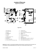
1. The Power VT gas valve and control train (gas
train) provided with the appliance must be
directly connected to the union piped out of the
burner. After the gas train is attached to the
burner, the gas supply can be connected to the
gas shut-off valve (gas cock) at the gas train
inlet. After gas plumbing is complete, verify the
gas train is adequately supported and connect
the conduit and multipin plug into the multipin
receptacle in the gas train conduit box.
2. Carefully study the burner start-up information
included in this manual.
Fill system tank with water. Some water boilers
may be equipped with an optional air vent. If
venting through the safety valve when filling the
boiler, insure gags or fixtures are removed from
the safety valve prior to start-up. Open the safety
valve to allow air in the tank to escape.
Be sure all connections into the tank are tight, as
leaks at tank fittings will damage the insulation.
3. The manual reset thermostat is a temperature
limiting safety device set at 215°F; the operating
thermostat is set at the factory at 180°F for on-off
operation. For two-stage models, a second
operating thermostat is used to control the
second stage operation and should be set
approximately 10°F below the primary operator.
Adjustment may be made by turning the
thermostat dial to the desired temperature.
CAUTION: CONDUCT THE FOLLOWING GAS TRAIN LEAKAGE TEST BEFORE
START-UP, AT ANNUAL INTERVALS AND PRIOR TO INVESTIGATING THE CAUSE OF
ANY REPORTED OCCURENCES OF DELAYED IGNITION.
1. Using an appropriate bubble detection solution,
thoroughly coat all gas train pipe connections. If
any bubbles are detected, the leaking connection
must be tightened, recoated, and rechecked to
assure stoppage of the leak.
2. Attach a manometer to measure the gas
pressure at the manual gas shutoff valve located
just upstream of the gas train. Adjust gas train
inlet pressure to the specified value (e.g. 14"
W.C.), and tightly close the gas train manual
shutoff valve closest to the burner.
3. Reattach the manometer to the gas train manual
shutoff valve at the burner and record the
measured gas pressure in inches of water
column (W.C.). Measure gas pressure again after
15 minutes. If gas pressure has increased 0.5"
W.C. or more, the gas leak must be isolated to
one or more of the operating gas valves. (For
example, a solenoid actuated gas shutoff valve.)
After any leaking valve is replaced, the
reassembled gas train must be leak tested again
before start-up is attempted.