
Operating instructions


- 6 -
8
2
9
2
8
1
2
3
5
6
7
9
10
11
4
2
5
4
7
8
6
12
13
14
9
10
1
11
3
11
3
54
8
1
2
7
2
11
1
113
4
10
9
7
8
9
1
2
2
1
5
SMD ##0-16
SMD ##2-16
SMD ##0-22 SMD ##2-22 SMD ##0-24 SMD ##0-25
1
2
5
9
10
8
3
7
11
4
2
5
9
10
8
4
6
3
1
7
5
4
3
107
6
8
1
1
3
4
5
6
7
8
6
2
1
54
3
7
SMD ##0-27 SMD ##2-27 BMD ##0-30 BMD ##0-32
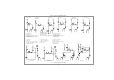
1 Flaschenventil
2 Anschlußwendel
3 Druckminderer einstufig: Typ ##0-xx
Druckminderer zweistufig: Typ ##2-xx
4 Vordruckmanometer
2
5
4
13
14
10
1
11
3
7
6
9
8
9 Spülgasausgangsventil
10 Spülgasausgang
11 Brauchgaseingangsabsperrventil
12 Spülgaseingang
13 Rückschlagventil
5 Hinterdruckmanometer
6 Brauchgasausgangsabsperrventil
7 Brauchgasausgang
8 Sicherheitseinrichtung: Abblaseventil
11
Abb.1: Fließschemata BMD und SMD
1 cylinder valve
2 spiral tube
3 press.reg. single stage: Typ ##0-xx
press.reg. double stage: Typ ##2-xx
4 inlet pressure gauge
9 purge gas outlet valve
10 purge gas outlet
11 process gas inlet shut-off valve
12 purge gas inlet
13 non return valve
fig. 1: flow scheme BMD and SMD
SMD ##0-24
SMD ##0-16
5 outlet pressure gauge
6 process gas outlet valve
7 process gas outlet
8 safety valve
12