
Operating instructions


- 10 -
For safe handling, gas cylinder locking
brackets are to be attached (accessory
available from the manufacturer).
5.2 Preparation
First, look at the rating plate and labelling
to check whether the pressure regulator is
suitable for the intended use (gas, pressure,
material).
Check whether the material of the subsequent supply line is
suitable for the gas in question. Then connect the supply
line to the process gas outlet at the station or battery
pressure regulator. For the screwed connection we
recommend compression ferrule connections. If ordered
together they are already sealed into the outlet of the
fitting. Assembly is carried out by inserting the pipe as far
as possible into the opening of the union nut. The union nut
is tightened securely, first by hand, then with an open-
ended spanner (1 ¼ turns).
If present, the relief valve and purge outlet are connected in
the same manner to an exhaust line. Please ensure that the
exhaust line leads to a suitable and safe location.
5.2.2 Connecting the connection spiral to the
gas cylinder
The threads of the cylinder valve and the
union nut on the spiral must be in perfect
condition.
Always use new seals. Seals must not be
deformed and traces of dirt and metal chips
must not be present.
Use only original DruVa cylinder connection
spirals which correspond to the gas type
used.
Check correct seating of seals in connector
of spiral.
Note whether the cylinder connection nut has a left-hand or
right-hand thread. Left-hand thread is indicated by a groove
cut round the outside of the nut. First screw the nut by hand
onto the cylinder valve thread; then tighten with an open-
ended wrench. At the same time exert counter-pressure on
the spiral line handle.
Do not use spanner extensions as the thread
and seal can be damaged. This can cause
leakage and uncontrolled emission of gas!
5.4 External gas purging
+
Stations with external gas purging make it
possible to:
dry the fitting and/or remove damp
atmospheric air which may have entered the
station before start-up or when changing
cylinders,
purge out toxic, corrosive or pyrophoric
gases from the fitting before changing
cylinders and before ending operation.
+
Dry, clean purging gas N
2
5.0 or Ar 5.0 is
required for successful purging.
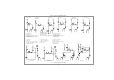
1. Check that the purge gas inlet (12), purge gas outlet (10),
process gas outlet (7) and connection spiral (2) are
connected correctly.
2. Close the process gas outlet valve (6), process gas inlet
valve (11) as well as the purge gas inlet valve (14) and purge
gas outlet valve (9) (handwheel of valves at right angles to
the pipe).
3. Close the pressure regulator (3) by turning the handwheel
anti-clockwise.
4. Open the purge gas inlet valve (14).
5. Open the process gas inlet valve (11).
6. Open the pressure regulator (3) partially by turning the
handwheel approx. two revolutions clockwise.
7. Close the purge gas inlet valve (14). Allow the purging gas
which has now flowed into the station to remain there for a
few seconds.
8. Open the purge gas outlet valve (9) briefly and allow the
purging gas to escape via the purge gas outlet (10). Then
close the purge gas outlet valve (9) again immediately.
9. Repeat steps 4., 7. and 8. between five and seven times.
10. Close all valves of the station. Close the pressure
regulator (3) completely by turning the handwheel
anticlockwise.
5.5 Start-up
Use only stations with external gas purging
when working with toxic, corrosive or
pyrophoric gases.
Before start-up you must look at the rating
plate to check whether the fitting in
5.2.1 Attaching the connection spiral to the
station
The stainless steel spiral line for connecting the station to
the gas cylinder is always supplied separately. First check
that the spiral line is suitable for the fitting. A number is
punched into the connecting nut of the spiral line. It
corresponds to the gas type allocation according to DIN 477.
There is only one version of connection spiral. It is equally
suitable for connecting station pressure regulators and
battery pressure regulators (left-hand and right-hand sides).
To attach the connection spiral to the station, first remove
the plastic protective caps from the connecting thread at
the station and from the spiral connecting nut. Please
ensure that the supplied flat seal is inserted in the union
nut. Then tighten the union nut on the connecting thread at
the station inlet; first by hand and then with an open-ended
spanner (SW 17).
5.3 Internal gas purging
+
Station or battery pressure regulators with
internal gas purging are applied to allow
removal of atmospheric air which enters the
system when cylinders are changed.
1. Close the purge gas outlet valve (9) as well as the
process gas inlet valve (11) and process gas outlet valve (6)
- if present (valve handle at right angles to pipe).
2. Close the pressure regulator (3) by turning the handwheel
anticlockwise.
3. Open the cylinder valve (1) slowly.
4. Allow the process gas to flow into the spiral line (2) and
allow it to remain there for a few seconds. Close the
cylinder valve (1) again.
5. Open the purge gas outlet valve (9) briefly and allow the
gas which is in the spiral line to escape. Then close the
purge gas outlet valve (9) again immediately.
6. Repeat steps 3. to 5. between five and seven times.
Operating instructions SMD, BMD