PureFlow AirDog Universal Fuel Module Upgrade Kit Installation Instructions This Kit Includes: Please verify all parts are included before beginning install. 1 set. Bulkhead Fitting, o-ring, washer & lock nut 1 ea. Grommet Adapter 1 ea. ½” male quick connect 5 ea. Wire clamps 2 ea Tie Straps 1 ea. OE style flexible fuel line 1 ea. Nylon suction tube 1 ea. Bracket, 2 ea.
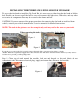
INSTALLING THE PUREFLOW® FUEL MODULE UPGRADE! To access the fuel tank to install the Up Grade Kit, it is necessary to either drop the fuel tank or lift the bed. Should you choose to pull the bed be sure to disconnect the light wires, filler tube, and any other accessories or components that may be secured to the frame and bed. CAUTION: If you are unsure of the proper procedure for removing the fuel tank or truck bed from vehicle, consult your vehicle manufacturer’s service manuals for detailed instructions.
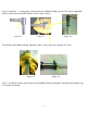
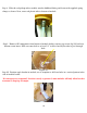
For Fuel Module “A” In-tank style Note: The sending unit pictured may not be the exact same as the one you have, however installation procedure will be similar on all sending units Step 2. Drill a 5/8 hole in the top of the Fuel Module (fig 5). Some modules can be drilled at the unused port (fig 6), with other versions it may be necessary to remove some ribs (on top of module only) and grind or sand flat before drilling hole to provide a good sealing surface.
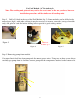
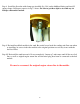
An alternate method is to cut the black plastic supports (there are 3) around the top of the pump that are attached to the basket and remove entire assembly, the end result will look like fig 9. This will expose a small rubber valve at bottom of module (fig 8) that will allow fuel to enter module from below. Note: Drill a ½” hole in the sides of the bucket 2-3” from the bottom. Figure 8 Figure 9 Step 4.
Step 5. Install the ½” quick connect fitting into the bulkhead fitting (fig 10). Use diesel compatible thread sealant tape on the NPT threads (arrow shows where). Figure 10 Figure 11 Figure 11A Step 6.Insert the bulkhead fitting with the washer, o-ring side down, into the 5/8” hole. Figure 12 Figure 13 Step 7. Install the washer and lock nut on the bulkhead fitting and tighten down onto the module (fig 12, washer not shown).
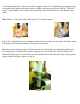
Step 8. Install the flex tube with clamps pre installed (fig 13A) on the bulkhead fitting and install 2 spring clamps 180 degrees apart as in fig 13 above. Be sure to get these tight as to avoid any air leakage when under suction. Figure 13a Step 9. Re-install modified module in the tank. Be careful to not bend the sending unit float arm when re-installing, be sure to index the module to the original position to avoid any issues with the fuel level float. Step 10. Re-install the tank into truck.
INSTALLING THE PUREFLOW® FUEL MODULE UPGRADE FOR FUEL MODULE WITHOUT THE IN-TANK PUMP Note: The sending unit pictured may not be the exact same as the one you have, however installation procedure will be similar on all sending units Step 1. Drill two ½” fuel ports in the side of the fuel basket, across from each other, about 3 inches from the bottom to allow more fuel into the basket.
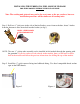
Step 3. Assemble the Pickup Tube as shown. Hold the assembly Next to the fuel module. Adjust the length of the pickup tube so that it is slightly longer than the module. When the pickup tube is installed, the two wire clamp and bracket will hold suction tube against the bottom of the fuel module collection basket. Step4. Remove the unused tube assembly and install the bulkhead fitting using the special grommet adapter. Figure 5 Figure 6 Step 5.
Step 6. Install the washer on the bulkhead fitting first then tighten the Nyloc nut. Figure 7 Figure 8 Step 7. When tightening the lock nut on the bulkhead fitting be careful not to damage or break the fuel module. Figure 9 NOTE: When modifying the fuel module, be sure to make a ¼” opening in the original suction line for the return fuel to escape into the basket. The original suction tube usually has a check valve to prevent loss of prime. DO NOT sever the line completely.
Step 8. Slide the soft pickup tube assembly onto the bulkhead fitting and fasten with supplied spring clamps as shown. Next, route soft plastic tube to bottom of module. Step 9. Remove OE components from bottom of module basket, remove top screen (fig 10) but leave bottom screen intact. Drill out center hole to at least 5/8” to allow hard Nylon tube to pass through hole. Figure 10 Step 10.
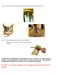
Step 11. Next drill two more holes, one on either side of where the tube will be in bottom of module (fig 11). Figure 11 Step 12. Slide the two wire clamp over the ring end of bracket (Fig 12), insert Nylon tube with the angle cut pointing to bottom of module (Fig 13), attach convoluted tube with spring clamp and secure bracket to module with supplied screws and lock nuts, make sure Nylon tube is at bottom of module where lower screen is.
End result: You should have a new suction tube that goes all the way down to the bottom of the sending unit, be sure to drill holes where instructed in order to pull a sufficient amount of fuel into the module. The stock suction/supply fitting on the top of the sending unit will now act as the return for the AirDog system, the new bulkhead fitting and suction tube will be for the AirDog suction line and then factory return line will be reconnected back to the sending unit in its factory position.