
User Manual

SPEAKER OUTPUT
COM
70V 100V
4Ω
8Ω
16Ω
+
- - -
+ +
a. b. c.
SPEAKER OUTPUT
COM
70V 100V
4Ω
8Ω
16Ω
+
- - -
+ +
a. b. c.
ATT IN
SPK OUT
SPEAKER OUTPUT
COM
70V 100V
4Ω
8Ω
16Ω
+
- - -
+ +
a. b. c.
ATT IN SPK OUT
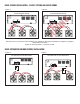
Correct Speaker Wiring
SPEAKER OUTPUT
COM
70V 100V
4Ω
8Ω
16Ω
+
- - -
+ +
a. b. c.
Incorrect Speaker Wiring
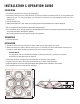
BASIC SPEAKER INSTALLATION - 70 VOLT SYSTEMS AND APPLICATIONS
BASIC ATTENUATOR/VOLUME CONTROL INSTALLATION
Full Remote Control Attenuation Zone Remote Control Attenuation
Figure 1.
Figure 3.
Figure 2.
Figure 4.
Be careful not to cross wires when installing your speakers. Wiring should always be negative to negative
and positive to positive
(Figure 2. shows speaker c. incorrectly wired).
W
R
ONG