
Manual


11
Installation
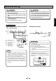
A 4-pin/8-pin separation-type connector is used for the signal connections on this
pump. The signal lead used is a multi-core round tough-rubber sheath cable.
Though the size of the signal lead differs according to the number of signals to be
used, select a signal lead that meets the following criteria:
• Cross-sectional area of 0.5 mm
2
or more
• O.D. 5 to 10 mm dia.
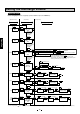
Electrical Wiring
Signal Lead Connections
(Example) 4-pin connector, OMRON XS2F-D421-D80A
1 (brown) : Pulse input (IN1)
2 (white) : Analog input (4 to 20 mA)
3 (blue) : Pulse input (IN2)
4 (black) : Common (COM1)
Pulse signal
Stop signal
Analog signal, etc.
1 (brown) IN1
2 (white)
4 (black)
3 (blue) IN2
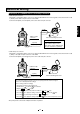
(Example) 8-pin connector, OMRON XF2F-D821-GHO-C (2 m)
COM1
Output 1
Output 2
1 (white)
IN3
2 (brown)
3 (green)
4 (yellow) OUT1 collector
5
(gray) OUT2 collector
6
(pink) Emitter
7 (blue) IN4
8 (shielded) Note 1
+5V
+
-
COM2
Reset
signal,
etc.
1 (white) : Digital input (IN3, high speed)
2 (brown) : +5 V power (sensor power supply)
3 (green) : Input common (COM1)
4 (yellow): Output 1 (OUT1, open collector)
5 (gray) : Output 2 (OUT2, open collector)
6 (pink) : Output common (COM2)
7 (blue) : Digital input (IN4, low speed)
8 (shielded): Shielded
Pulse
signal,
etc.
NOTE1: Keep "8" shield open without connecting to the ground.
NOTE2: Above pin layout shows the connector side. Accordingly the
pump side should be viewed reversed.
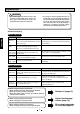
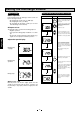
●Pulse signal
Distribution of Signal Leads
PZiG
O.C. or
no-voltage
contact signal
COM
Approx.
2 mA
Approx.
2 mA
Approx.
2 mA
N units ✕ 2 mA
COM COM
Multiple PZiGs can be connected in parallel.
PZiG
PZiG
PZiG
+
+
-
-
+
-
Analog signal
Multiple PZiGs can be arranged in series.
PZiG
110 110
●Analog signal
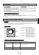
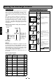
START
STOP
MODE FUNC
RESET
SET
ALARM
AUTO
PL
For 4-pin connector
For 8-pin connector
Not used
05-45_PZiG Series(2)English 06.8.4 9:39 AM y[W 11