Solenoid-Driven Metering Pump PZiG Series USER'S MANUAL Before beginning operation, read this User's Manual carefully! Ignoring the descriptions in this User's Manual and mishandling the unit may result in death or injury, or cause physical damage. Applicable Models PZiG-300 PZiG-500 PZiG-700 PZiG-1000 PZiG-1300 ¡Be sure to keep this User's Manual in a place where it will be easily available for reference.
For the Safe Use of This Product This User's Manual is intended to help the operator to handle the product safely and correctly. In support of this aim, important safety-related instructions are classified as explained below. Be sure to follow them at all times. ! WARNING ¡If the product is operated incorrectly in contravention of this instruction, it is possible that an accident resulting in death of serious injury will occur.
¡When a tightening valve is located on the discharge piping, and when there is a risk of blockage, be sure to install a relief valve on the piping immediately on the discharge side of this pump. When a valve has been tightened or foreign matter clogs the discharge piping of the pump, the pressure in the pump may increase beyond the range indicated in the pump specifications. This may result in chemicals spurting out, damage to the piping or malfunction of the pump, which are dangerous.
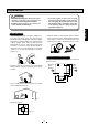
Other ! CAUTION ¡Do not remodel this pump. ¡Adopt preventative measures such as a chemical drain ditch in case chemicals flood out of the pump. Also, install so that the chemical level does not rise up to the surface where the pump is installed. ¡When disposing of used pumps, ask an authorized disposal expert to dispose of the pump in accordance with local laws and regulations.
Contents Explanation of Product ................................................................................................................5 Names of Parts .............................................................................................................................5 Outline Outline Installation Installation Installation.....................................................................................................................................6 Piping........................
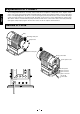
Explanation of Product Outline The metering pump PZiG Series accurately feeds a fixed amount of liquid for a fixed period of time. Liquid is fed by action of the check valve inside the pump head and volumetric changes in the pump head that occur by reciprocating motion of the diaphragm driven by the force of the electromagnet (solenoid). This structure ensures that the discharge volume per single operation of the pump is fixed. The pump can be used on a power supply within the voltage range 90 to 264 V.
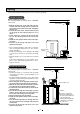
Installation ! WARNING ¡This pump is not designed to explosion-proof specifications. It cannot be used in explosion-proof areas, and in explosive/ignitable atmospheres. ¡Install the pump in locations out of reach of personnel other than an administrator.
Piping This section mainly describes hose connection type piping. Contact TACMINA separately for details of other types of piping. Requests during Piping Installation ●Pulsation • The hoses on this pump vibrate as this pump generates pulsation. Secure this pump in such a way that hoses do not vibrate. • We recommend installing a damper to reduce pulsation. Contact TACMINA separately.
Piping The following examples show layouts for a hose connection type pump. Flooded Installation ●Floor installation procedure The following explains an example where a TACMINA tank is used. 4 5 Check valve Installation 1Remove the hose nut on the tank side, pass the suction-side hose through the nut, connect the hose to the suction valve on the tank, and tighten the hose nut. 2Connect the hose to the suction-side hose joint on the pump by the same procedure as in (1) above.
Piping Hose Connections Installation • Insert hoses sufficiently and firmly tighten hose nuts to prevent hoses from becoming disconnected. Do not tighten them with a tool using excessive force. Doing so might damage the hose. • When liquid temperature or ambient environmental temperature is higher than room temperature, hoses may become disconnected. Re-tighten nuts as required after pump operation is started. • When tightening the hose nut, hold the hose firmly to prevent it from twisting.
Electrical Wiring ! ! WARNING CAUTION ¡Electrical wiring must be performed by personnel such as an electrician having specialist knowledge. ¡Check the power voltage before wiring. Do not wire a power supply outside of the rated voltage range. ¡Be sure to ground the earth lead (green) when wiring to prevent electric shock. Installation ¡Do not operate this pump with wet hands. Doing so might result in electric shock. ¡Do not turn the power ON during electrical wiring.
Electrical Wiring Signal Lead Connections A 4-pin/8-pin separation-type connector is used for the signal connections on this pump. The signal lead used is a multi-core round tough-rubber sheath cable. Though the size of the signal lead differs according to the number of signals to be used, select a signal lead that meets the following criteria: • Cross-sectional area of 0.5 mm2 or more • O.D. 5 to 10 mm dia.
Electrical Wiring Connection to a TACMINA Pulse Transmitting Flow Meter • Cable w/ 4-pin connector Bring leads 1 (red) and 3 (white) of the 3-core cable provided with the flow meter together, and connect them to lead 1 (brown) of the cable w/ 4-pin connector on the PZiG. Connect lead 2 (black) to lead 4 (black) of the same cable w/ 4-pin connector.
Operation ! WARNING ¡When handling liquid-end sections, be sure to wear protective coverings (rubber gloves, mask, protective goggles, chemical-resistant overalls, etc.) appropriate for the chemicals be using used. ¡If you forget to open the discharge-side valve or if foreign matter clogs the discharge-side piping, the pressure in the pump and pump head may increase beyond the range indicated in the pump specifications.
Air Release ! IMPORTANT WARNING ¡During air release, chemicals spray forcefully from the tip of the piping. Either release air using water or other safe liquid, or return the tip of the air release piping to the tank. ¡Release air before pump operation when using the pump for the first time or when replacing the chemical container. Release Air by the Following Procedure (1) Release the pressure on the discharge-side piping to air.
Setting the Discharge Volume Operation Flow Before changing the mode, stop pump operation and then press the MODE key. [Operation mode] [Stop mode] Operation in progress Pump stopped spm Manual MAN STOP ・ START [Setup mode] Changing setting values Manual MAN spm STP * This setting can be changed even during pump operation. MODE Operation % Manual MAN STOP ・ START Manual MAN % STP * This setting can be changed even during pump operation.
Setting the Discharge Volume Calibration The calibration procedure is as follows. The figures below are for a PZiG-1000. (1) Install the pump and pump to match the actual piping conditions, and set to the trial operation mode (2) Pour the solution to be actually used into a measuring utensil (e.g. graduated cylinder) capable of measuring the maximum discharge volume per minute of pump operation. (3) Insert the suction-side end of the pump piping into the graduated cylinder, and release air.
Setting the Discharge Volume Manual Mode Setting Manual Mode (changing the number of strokes) ●Basic operation In the manual mode, the discharge volume can be set by the following methods: • By changing the stroke spm (1 to 300 spm) • By changing the ratio (1 to 100%) • By changing the discharge volume (0.1 to maximum discharge volume mL/min) Display Operation Explanation START In the manual mode, the number of strokes can be changed during pump operation or when pump operation has stopped.
Setting the Discharge Volume Setting Manual Mode (changing the ratio) Display Operation Explanation START In the manual mode, the ratio can be changed during pump operation or when pump operation has stopped. STOP MODE Setting Manual Mode (changing the discharge volume) Display Operation Explanation START In the manual mode, the discharge volume can be changed during pump operation or when pump operation has stopped.
Setting the Discharge Volume Analog Mode Setting Scaling in the Analog Mode In the analog mode, analog signals from an external device are received, and automatic operation is performed within the range 0 to 300 spm according to the setting values (set point (SP), and proportional band (PB)). First, perform scaling according to the application of this pump, and then set the set point.
Setting the Discharge Volume Set Point/Proportional Band in the Analog Mode ●Set point (SP) For the set point (SP), set a target value on the X-axis (horizontal axis). Setting the Set Point/Proportional Band in the Analog Mode Display 100% (300spm) Operation START 50% (150spm) PB:-50% STOP PB:50% PB:100% PB:-100% MODE 0% (0spm) Ex: Set point (SP) 0 0.0 0.0 50 7.0 1.00 If the screen on the left is not displayed, press the MODE key until it is displayed. 100% 14.0 pH 2.
Setting the Discharge Volume Pulse Frequency-division Mode Setting Pulse Frequency-division Mode ●Basic operation 1Pulse signals from the outside are received, and automatic operation is performed according the frequency-division ratio setting. 2The frequency-division ratio can be set within the range 1/1 to 1/9999.
Setting the Discharge Volume Pulse Multiplication Mode Setting the Pulse Multiplication Mode ●Basic operation 1Pulse signals from the outside are received, and automatic operation is performed by the number of strokes corresponding to the preset multiplication. 2The multiplication can be set within the range 1 to 9999. at this time, the pump operates at the number of operation strokes (spm) set in the manual mode.
Setting the Discharge Volume Count Mode Setting Count Mode ●Basic operation 1The start signal is received and the pump operates for the number of preset times. (batch processing) 2The setting value can be set by a combination of 1 to 9999 times and ✕1, ✕10, ✕100, ✕1000 multiplication. (1 to 9999, 10 to 99990, 100 to 999900, 1000 to 9999000) 3The start signal can be selected from an external input and START/STOP key. 4The end signal can be output when operation when operation for the preset count ends.
Setting the Discharge Volume Interval Mode Setting the Interval Mode ●Basic operation 1Intermittent operation by the preset ON and OFF times is repeated. * The ON/FF state during a start can be changed by parameters. 2The setting values of each of the ON and OFF times is set from to 1 to 9999 minutes (in 1-minute increments). 3Operation can be paused by input of an external stop signal.
Key Lock Keys can be locked to protect setting values. The STOP/START key can be operated even when the key lock is active. (1) Set the mode that you want to lock, and press the STOP key to stop the mode. START STOP STP is displayed to indicate that the mode is stopped. (2) Hold down the SET key for at least two seconds with the FUNC key held down. FUNC + SET RESET This enables the key lock, and operations other than the STOP/START key are disabled.
Maintenance ! WARNING ¡When handling liquid-end sections, be sure to wear protective coverings (rubber gloves, mask, protective goggles, chemical-resistant overalls, etc.) appropriate for the chemicals be using used. ¡Do not turn the power ON during maintenance. Attach a "Work In Progress" label to the power switch. ¡Before disassembling liquid-end sections, be sure to release the discharge-side pressure, drain the chemicals from liquid-end sections, and wash them.
Replacing the Diaphragm IMPORTANT 1 When fixing the pump head using the head bolts, tighten the bolts in the order shown below a little at a time using even force. For example, tightening will be uneven if the bolts are tightened in the order 1, 3, 5 and 2. This might cause chemicals to leak from the pump head. 3 6 5 2 4 Removing the Pump Head 1Remove the six head bolts. 2Remove the pump head. Maintenance 1 2 Replacing the Diaphragm/Protective Diaphragm 3Remove the diaphragm.
Replacing the Valve Seat and Check Ball • Attach O-rings, ball stoppers and check balls making sure that they face the correct direction. • When removing and re-fitting in the upper/lower joints, make sure that you do not mistake the upper and lower joints. • Also, make sure that the O-rings and check balls are not scratched, and dust or dirt is not sticking to the valve seat.
PZiG-300/500/700/1000/1300-VTCF (High viscosity specification) Union nut Union nut Union joint Union joint O-ring* O-ring* 2nd joint 2nd joint MNPT3/4 FNPT3/4 Joint VP20 Ball guide Coiled spring* Check ball* O-ring* 1st joint Maintenance Washer O-ring* Hexagon head bolt Spring Washer O-ring* 1st joint O-ring* Ball guide Coiled spring* Check ball* O-ring* Joint FNPT3/4 MNPT3/4 2nd joint 2nd joint O-ring* O-ring* Union joint Union joint Union nut Union nut VP20 *Consumable 29
PZiG-300/500/700-FTCT 12 x 15PTFE PZiG-1000/1300-FTCT Hose nut 12 x 15PTFE FNPT1/2 FNPT1/2 Discharge side joint Hose nut Joint Hose joint Hose joint Ball guide O-ring* Valve stopper Check ball* Check ball* O-ring* 1st joint Washer Discharge side lower joint Spring washer O-ring* Pump head Hexagon head bolt Washer Pump head Hexagon head bolt O-ring* 1st joint O-ring* O-ring* Ball guide Valve stopper Check ball* Check ball* Joint Suction side joint Hose joint FNPT1/2 Hose joint 12 x 15PT
Setting Parameters For defaults, see page 32. Setting Parameters Display Parameter Setup Flow Operation Explanation Make sure that STP, MAN and spm are displayed. Manual STP SET + Hold down the key for at least five seconds while pressing the SET key in the stop condition in the manual mode. FUNC FUNC FUNC FUNC P --- 01 P --- 02 P --- 03 P --- ** SET RESET *P-01 cannot be set as it is used for internal processing. SET Change settings. SET Change settings.
Setting Parameters Parameter List No. Item Details Internal proP-01 cessing P-02 P-03 Digital input P-04 P-05 Input 1 Input 2 Input 3 Input 4 P-07 Parameter Default Explanation 0 Used for internal processing. Cannot be set by the user. See Table 1. See Table 1. See Table 1. See Table 1. 1 2 3 4 Can be selected from Table 1. Only the selected function is enabled. Output 1 See Table 2. 1 Output 2 See Table 2.
Troubleshooting ! WARNING ¡Do not operate this pump with wet hands. Doing so might result in electric shock. ¡Make sure to turn OFF the power before disassembling the liquid end and check that the power is not applied to the pump. Do not start the disassembly only by stopping the pump with a key. Attach a "Work In Progress" label to the power switch so that the power cannot be turned ON during repair works.
Troubleshooting Troubles in the Signal Input Mode Details of Trouble Cause Remedy Signals are not input according to preset division or multiplication ratio. (during pulse signal input) (1) Noise on signal line (1) Move the signal line away from the power line. Or, use shielded cable for the signal line. Signal does not reach 20 mA. (during analog signal input) (2) Insufficient signal drive (2) Check the maximum drive resistance of the signal source. Keys other than START/STOP key do not function.
■Model Codes PZiG - 1300 - V T C E - 12x18PVC - W - S - JPL - X 1 2 3 4 5 6 1Series name 7 8 9 0 q 7Connection PZiG Series Type 2Pump model Type Discharge Volume 300 340mL/min 500 530mL/min 700 760mL/min 1000 1000mL/min 1300 1300mL/min 12 x 18 PVC PVC braided hose 12 x 18mm dia. 12 x 15 PTFE PTFE tube 12 x 15mm dia.
■Performance Specifications Model Specifications L/H Max. discharge volume 500 700 1000 1300 20.4 31.8 45.6 60.0 78.0 mL/min 340 530 760 1000 1300 G/H (US) 5.39 8.40 12.0 15.8 20.6 1.1 1.8 2.5 3.3 4.3 1.0 * 0.7 * 0.4 0.3 0.2 Discharge volume per stroke (mL/stroke) MPa Max. discharge pressure 300 bar 10 7 4 3 2 psi 145 101 58 43.5 29 Max. number of strokes (spm) 300 Stroke length (mm) 1.
■I/O Signal Specifications ¡4-pin connector Category Name Digital signal input [pulse signal input] Type Connection Pin No. Standard Max. response speed 125 Hz (duty 50%) No-voltage contact 1-4 Input resistance: approx. 2 kΩ O.C (IN1, high speed) Damping 1 sec or less DC 2-4 Analog signal Input Input resistance: approx. 110 Ω 4 ~ 20mA Max. response speed 10 Hz (duty 50%) Digital signal input 2 No-voltage contact 3-4 Input resistance: approx. 2 kΩ non-lock operation [stop signal input] O.
■Performance Curves The following performance curves are measurement examples obtained by measuring on test equipment at TACMINA. These performance curves may differ slightly depending on various on-site conditions and product differences. Measure the discharge volume under actual operating conditions, and set the strokes according to the performance curve that is obtained.
■Discharge Performance of High-viscosity Liquids ■Length of Discharge-side Piping and Discharge Volume When a fast stroke speed is set for transferring highviscosity liquids, piping resistance on the suction side may cause the amount of sucked in liquid to be reduced. The graph below shows the relationship between piping length and discharge volume. Installing a damper lessens piping resistance and allows the length of the piping to be extended.
■External Dimensions (mm) PZiG-300/500/700/1000/1300-VTCE/VTCF-12 x 18PVC-WA B C D E PZiG-300/500-VTCE/VTCF-12 x 18PVC-W- 112 224 282 49.5 246 103 206 273 53.5 253 PZiG-700-VTCE/VTCF-12 x 18PVC-W- PZiG-1000/1300-VTCE/VTCF-12 x 18PVC-W- 105 210 275 53.5 253 14 170 A C B A 150 165 38 32 D 170 E PZiG-300/500/700/1000/1300-VTCE/VTCF-FNPT1/2-WA PZiG-300/500-VTCE/VTCF-FNPT1/2-W- C D E 100 200 270 49.5 246 PZiG-700-VTCE/VTCF-FNPT1/2-W- 90 180 260 49.
■External Dimensions (mm) PZiG-300/500/700/1000/1300-VTCF-VP20-VA B PZiG-300/500/700-VTCF-VP20-V- 249 49.5 PZiG-1000/1300-VTCF-VP20-V- 253 53.5 B A PZiG-300/500/700/1000/1300-VTCF-FNPT3/4-VA B PZiG-300/500/700-VTCF-FNPT3/4-V- 249 49.5 150 14 Specifications 170 124 294 248 124 PZiG-1000/1300-VTCF-FNPT3/4-V- 165 32 38 170 B A 41 253 53.
■External Dimensions (mm) PZiG-300/500/700/1000/1300-VTCF-MNPT3/4-VA PZiG-300/500/700-VTCF-MNPT3/4-V- 246 49.5 PZiG-1000/1300-VTCF-MNPT3/4-V- 253 53.5 308 14 170 154 324 154 150 B 38 165 32 B 170 A PZiG-300/500/700/1000/1300-FTCT-12 x 15PTFE-WA PZiG-300/500/700-FTCT-12 x 15PTFE-W- 115 PZiG-1000/1300-FTCT-12 x 15PTFE-W- B C D E F 97 212 285 49.5 246 128 128 256 298 53.
■External Dimensions (mm) PZiG-300/500/700/1000/1300-FTCT-FNPT-1/2-WA B C D E F 97 212 285 49.5 246 PZiG-300/500/700-FTCT-FNPT-1/2-W- 115 PZiG-1000/1300-FTCT-FNPT-1/2-W- 128 128 256 298 53.
Consumables and Spare Parts ■Consumables The recommended replacement cycles are for cases where the pump is operated under constant conditions (room temperature and clean water). These cycles change according to individual site conditions. Use these cycles as rough guidelines for replacing consumables. Neglecting to replace consumables may cause defective discharge (injection) or malfunction.
Customer Services If you are unsure about customer services (e.g. repair within the warranty period), please contact your supplying agent. Warranty Repair ■Warranty Period and Scope of Warranty ■When requesting repair (1)The warranty period is one year from the date of purchase. Before requesting repair, thoroughly read this User's Manual and re-inspect the product. If a malfunction is observed, ask your supplying agent for repair.
Head Office: 2-4-8 Minami-Semba, Chuo-ku, Osaka 542-0081 Japan Tel. +81(0)6-6271-3974 Fax. +81(0)6-6271-4677 URL http://www.tacmina.com E-mail trade@tacmina.com Europe Representative Office: Hochstr. 35 56235 Ransbach-Baumbach, Germany Tel. +49(0)2623-928-345 Fax. +49(0)2623-928-507 E-mail trade@tacmina.com Southeast Asia Representative Office: 20/1 Soi Ramkhamheang 16, 2nd. Branch Ramkhamheang Rd., Huamak, Bangkapi, Bangkok 10240 Thailand Tel. +66(0)2319-9315 or 9316 Fax.