
Manual

9
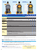
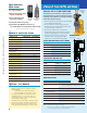
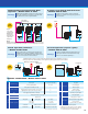
CONTROL VARIATIONS – Models PZi8 & PZiG
M
ulti-liquid Proportional Flow Rate
Injection – Models PZi8* & PZiG
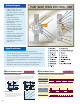
Multiple PZiGs inject different chemicals according to preset
values while calculating the signal from a single flow meter.
This eliminates the need for a signal distributor.
Advantage
2
-point Level Switch-based Control
– Models PZi8 & PZiG
A 2-point level control enables output of an alarm at
the liquid level “low limit” and stops pump operation at
the “low-low limit.”
Advantage
Batch Injection (counter)*
– Models PZi8 & PZiG
Pump operation starts on command signal. Operation auto-
matically stops and operator is notified of completion when
a preset count is reached. Maximum number of pulses 9999x1,
x10, x100 or x1000 (555 hours max. run time).**
Advantage
Interval Injection (repeat cycle)*
– Models PZi8 & PZiG
The pump is repeatedly started and stopped by a preset
timed program. ON time and OFF interval can be easily
set from 1 to 9999 minutes respectively.**
Advantage
PZiG
C
PZiG
B
PZiG
A
Flow meter
(pulse/analog)
Sodium
h
ydroxide
Sodium
h
ypochlorite
Polyaluminum
c
hloride
S
PZiG
system
P
PZiG
P
Alarm
PZiG
system
PZiG
F
Start signal
Discharge completed display
PZiG
system
PZiGP
Stop signal
PZiG
system
P
Note:
Multiple PZiG pumps take pulse or analog signal directly: A single PZi8 pump would
take a pulse or analog signal directly and slave a second or third pump to its output.
*Input is
connected to
one PZi8 pump:
Multiple PZi4
pumps would
follow the pulse
output of the
PZi8 pump.
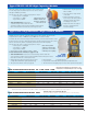
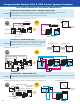
Adjustment range
Stroke speed 1~300 spm (1 spm step)
Stroke length adjustment 20~100%*
Analog input 4~20 mADC (110 ohm) 1
Number of inputs Digital input high speed (125 Hz max.) Open collector 2
Digital input low speed (10 Hz max.) Open collector 2
Other Power supply output +5VDC (10 mA max.) 1
LCD display Display unit selection (%, mL, spm)
Manual operation Manual mode
Analog mode Analog signal 4~20 mADC
Pulse signal 1/1~1/9999
Automatic operation Pulse signal 1 to 9999 times
Count mode Number of strokes 1~9999 (x1, 10, 100, 1000)
Interval mode ON/OFF time 1 to 9999 mins / 1 to 9999 mins
*50~100% for sizes -31/-61/-12
Stop input
Level switch input
Control input
Alarm reset input
Start/reset input
Operation signal output
Control output Operation sync pulse output
1
End signal output
2
Analog input error alarm
3
Inpule pulse buffer overflow alarm
3
Alarm output
Level error alarm
3
Injection monitor error alarm
3
1. Output in sync with solenoid operation.
2. Output when operation for preset count is completed.
3. Alarm display, alarm output and pump operation can
be selected in response to an alarm condition.
Basic specifications
Inputs
Run mode
Outputs
*Calibration function assures accuracy greater than ordinary pumps in these applications (see page 3).
**Pump operation can be interrupted by a remote signal at any time; program resumes when restarted.