
Manual
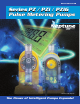

Type PZD/PZi-32/52 High Capacity Models
3
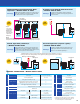
Available Only in Programmable Models
(See page 8 for Direct Connection of pH and Residual Chlorine Control Instruments)
Type PZiG Programmable Large Volume Models
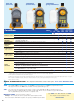
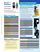
PZD Series pumps offer higher capacities. These models feature
an extra large keyboard and the injection rate can be entered
directly in milliliters per minute.
The injection rate can be set three ways by direct entry of:
– Stroke speed: 1 to 300 spm
– Percentage: 1 to 100%
– Injection rate: ml/min.
• Onboard calibration measures the
actual discharge volume under the exact
operating condition of the specific installation and chemical,
then stores that value to insure the correct injection rate.
High Capacity models are
available in material codes
VFC, VEC, SS and FTC only.
VFC model is shown.
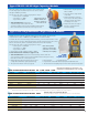
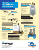
PZiG
with VTCF
Liquid Head
• Manual stroke length adjustment
20% to 100%.
• Set points can be easily viewed
on the LCD.
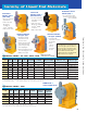
• Pump head may be rotated to
face in any of the three positions
other than where the keypad
and display are located.
• Pump head can be decoupled
from the controller base for
remote mounting.
PZiG Models offer capacities typically requiring motor driven pumps. Special models
easily handle viscosities of 1000 CPS (up to 4000 CPS at reduced volume).
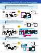
Powerful onboard controls allow proportional flow rate, pH and residual chlorine control
by direct analog connection eliminating the PID Controller and Inverter (plus the control
panel to house them), that are required by similar sized motor driven pumps.
The injection rate can be set three ways by direct entry of:
– Stroke speed: 1 to 300 spm
– Percentage: 1 to 100%
– Injection rate: ml/min.
• Manual stroke length adjustment 20% to 100%.
Control Functions also include (see pages 8 & 9):
• Onboard calibration measures the actual discharge volume under the
exact operating condition of the specific installation and chemical, then stores
that value to insure the correct injection rate.
• Multi-pump proportional flow rate injection from
a single direct flowmeter signal (pulse/analog).
• Two point level switch control (see page 9)
Note: Install a pulsation
dampener for discharge lines
greater than 7 feet to achieve
maximum pressure capability.
• Batch injection • Interval injection
• Proportional control with shift and proportional band function.
• Two line LCD screen displays injection rate and/or operational progress.
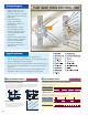
TYPE & SIZE SELECTION CHART: PZiG
PROGRAMMABLE MAX. CAPACITY MAX. PRESSURE DRAWING/ STROKE MAX. POWER AVG. POWER
MODEL GPD GPH ML/MIN. PSI CURVE LENGTH (MM) (VA) (WATTS)
PZiG-300 130 5.4 340 140 page 7 1.5 750 100
PZiG-500 200 8.4 530 100 page 7 1.5 750 100
PZiG-700 288 12.0 760 60 page 7 1.5 750 100
PZiG-1000 380 15.8 1000 45 page 7 1.5 750 100
PZiG-1300 495 20.6 1300 30 page 7 1.5 750 100
TYPE & SIZE SELECTION CHART: PZ / PZD / PZi4 / PZi8
MANUAL EXTERNAL PROGRAMMABLE MAX. CAPACITY MAX. PRES. DWG./ STROKE MAX. PWR. AVG. PWR.
MODEL INPUT MODEL
1
MODEL
1
GPD GPH ML/MIN. PSI CURVE LENGTH (MM) (VA) (WATTS)
PZ-31-HP
2
PZi4-31-HP
2
PZi8-31-HP
2
10.5 0.44 28 220 page 7 1.0 200 15
PZ-31 PZi4-31 PZi8-31 12 0.5 30 140 page 7 1.0 200 15
PZ-61 PZi4-61 PZi8-61 24 1.0 60 115 page 7 1.0 250 18
PZ-12 PZi4-12 PZi8-12 38 1.6 100 60 page 7 1.0 250 18
PZD-32 PZi4-32 PZi8-32 137 5.7 360 45 page 7 1.5 500 30
PZD-52 PZi4-52 PZi8-52 204 8.5 540 30 page 7 1.5 500 30
NOTES:
1
PZi4 models include 2-meter cable with 4-pin connector on one end; PZi8 models include separate 2-meter signal cables, one each with 4-pin and 8-pin connector end.
2
High Pressure models are available as PZ-31, PZi4-31 or PZi8-31 only; available in FEC or SS only. Refer to Material Code Chart on page 4.
Head can be turned 90° to allow base to be
mounted to a vertical wall (-31/-61/-12 only).