for NEPTUNE SERIES 6000 “dia-PUMP” MODELS 6100 thru 6250 Lansdale, PA. 19446 • Tel.
WARNING LOCKOUTS ARE REQUIRED BEFORE SERVICING THIS EQUIPMENT. SAFETY INSTRUCTIONS: Shut off/Lockout pump Power before Servicing. Be certain pump isolation valves are Closed and chemical is shut off. Bleed pressure before servicing.
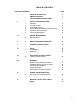
TABLE OF CONTENTS SECTION PARAGRAPH I GENERAL DESCRIPTION LIMITED WARRANTY PARTS ORDERING INSTRUCTIONS 4 5 6 1 2 3 4 5 6 INSTALLATION INSTRUCTIONS GENERAL SUCTION PIPING DISCHARGE PIPING ADJUSTMENT OF INTERNAL RELIEF VALVE INSTALLATION OUTDOORS STARTUPPROCEDURE 7 8 8 8 10 11 7 NORMAL MAINTENANCE MAINTENANCE 12 8 MOTOR OPERATING CONDITIONS 13 TROUBLE SHOOTING CHART 14 PARTS SPAREPARTS PARTS LIST 15 15 17 ELECTRONIC STROKE CONTROL SPECIAL INSTRUCTIONS 19 DRAWINGS DIRECTION OF MOTOR ROTATION
SECTION I GENERAL DESCRIPTION The Neptune Series 6000 “dia-PUMP” is a reliable metering pump of the high-pressure diaphragm type. Under constant conditions of temperature, pressure, and capacity adjustment settings, a +/- 1% metered discharge volume is maintained. A plunger reciprocating at a fixed stroke displaces hydraulic fluid, which actuates a flexible, chemically inert, Teflon diaphragm to create pumping action.
SECTION I NEPTUNE CHEMICAL PUMP COMPANY LIMITED WARRANTY All Neptune Pumps are tested at the factory prior to shipment. Each part used in their construction has been carefully checked for workmanship. If the pump is installed properly, Neptune Chemical Pump Company, Inc.
SECTION I PARTS ORDERING INSTRUCTIONS The complete model number and serial number of the pump must be furnished to insure prompt and accurate parts service. These numbers are found on the name plate (sample below) located on the side of the pump. Refer to Section VI for complete parts lists. Send all orders or inquiries for parts to: Parts Department Neptune Chemical Pump Company, Inc. P.O. Box 247 Lansdale, PA 19446 Tel.
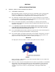
SECTION II INSTALLATION INSTRUCTIONS 1.0 GENERAL (REFER TO PARTS DRAWING ON PAGE#16) 1.0.1 UNPACKING & INSPECTION When unpacking a pump or chemical feed system, be certain that no parts are thrown away. Examine the equipment for possible damage. If damage has occurred, file claim with the common carrier within 24 hours. Neptune will assist in estimating the repair costs. 1.0.2 The “dia-Pump” should be located on a level surface.
1.0.8 Fill gearbox and pump by pouring the hydraulic fluid (drive lubricant) supplied through the fill opening at the rear of the pump. Pour fluid in slowly until it covers the worm gear. The control knob should be in the zero position during the filling. PLEASE NOTE: TO VENT THE AIR, REMOVE VENT PLUG LOCATED ON TOP OF THE OIL HEAD (# 54 on Parts Drawing). Allow 30 minutes for hydraulic fluid to make its way into pump chamber and then recheck fluid level.
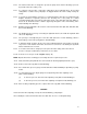
4.0.2 The internal relief valve is designed to protect the pump itself should a discharge pressure beyond the relief valve setting occur. 4.0.3 If a customer order specifies a relief valve setting above those indicated above, the specified setting will be set at the factory. All pumps are tagged with the relief valve setting used by the factory. 4.0.
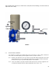
Take out Relief Valve cap to access Relief Valve screw (#32 on Parts Drawing). Insert Hex wrench to adjust relief valve setting. FIGURE 2 5.0 INSTALLATION OUTDOORS The “dia-Pump” is a totally enclosed pump, which can be used outdoors or indoors. When installed outdoors, make sure that the pump is protected against extremes of nature as follows: 5.0.1 Running of the pump when exposed to tropical sunshine with ambient temperature above 90°F (32°C) would cause excessive oil and motor temperatures.
6.0 START UP PROCEDURE The following start up procedure is complete and does repeat instructions on filling the gearbox and pump. 6.0.1 6.0.2 6.0.6 6.0.3 Remove backpressure spring, if any (anti-siphon spring, Part#100198 on Fig 3) for start up. Reinstall after pump is operational if needed. Flooded Suction: Refer to Section II, Paragraph 1.0.9, for instructions on filling gearbox with hydraulic fluid. On initial start-ups: Set the pump capacity at 0%.
SECTION III NORMAL MAINTENANCE 7.0 MAINTENANCE Under normal conditions, the “dia-Pump” should not require any significant amount of maintenance. It is advised that periodic visual observations be made of the oil level to make sure that it is over the worm gear. The liquid end of the pump should also be inspected for leakage. These observations should be made regularly. The hydraulic fluid should be drained and replaced twice a year, using the drain plug (# 68 on Parts Drawing) at the back of the pump.
7.1.5 Remove sealing nut (#39 on Parts Drawing) 7.1.6 Remove seal plate (#38 on Parts Drawing) using small brass hook to pry loose 7.1.7 Replace control rod “0” ring (#50 on Parts Drawing) & BACKUP RINGS (#51 on Parts Drawing) 7.1.8 When replacing sealing plate take care so as to not shear the sealing plate “0” ring and backup ring (#52 and #68 on Parts Drawing). Apply grease to “0” rings before assembly.
SECTION V TROUBLE SHOOTING CHART SYMPTOMS 1. Pump Motor Will Not Operate. CAUSES A. Blown Fuse. Check for short circuit or overload Reset. D. E. F. Open thermal overload device in starter. Low liquid level in tank (where low level cut-off is used). Broken wire. Low voltage. Oil “frozen” in pump. A. Starved suction. Replace suction piping with larger size. B. Leaky suction piping. C. Excessive suction lift. D. Liquid too close to boiling point.
SECTION VI 9.0.1 SPARE PARTS 9.0.2 Important—When ordering spare parts, please show MODEL NUMBER AND SERIAL NUMBER of pump for which parts are being ordered. This information can be found on a stainless steel nameplate riveted to the side of the pump. 9.0.
PARTS LIST FOR PUMP MODELS 6100 to 6250 (REFER TO PART DRAWING ON PAGE 16) ITEM# DESCRIPTION QTY. PART# 1 2 3 Gear Box Thrust Washers Worm Gear 58 SPM Worm Gear 117 SPM Eccentric Gear Shaft Shaft Retainer O-Ring Gear Shaft Retainer Screws Gear Shaft Retainer 3/8” Lock Washers 3/8-16 X 1" lg.
SECTION VII SPECIAL INSTRUCTIONS FOR SERIES 6000 “dia-PUMPS” WITH ELECTRONIC STROKE CONTROL MODEL #SM-1020 Neptune Electronic Stroke Control Unit adjusts the capacity of the 6000 Series Pump over its full operating range by changing the stroke length in response to an external signal. Manual hand crank is optional. Neptune Electronic Stroke Control consists of a Linear Actuator with required fittings and Adapters needed to mount the Actuator on a Neptune 6000 Series Pump.
SECTION IX DOUBLE DIAPHRAGM OPTION Special Instructions for Series 6000 “dia-Pumps” with Double Diaphragm The instructions below are for Neptune’s optional Double Diaphragm Kit. Use of a double diaphragm allows diaphragms to be monitored and provides an early warning upon failure of either diaphragm allowing repairs to be made before process fluid can mix with the pump’s hydraulic fluid.
11.0.9 Remove the vacuum pump. Plug valve Item No. 5 with a 316SS pipe plug Item No. 12 (Figure 5) 11.0.10 Reinstall the Pump 11.0.11 Follow procedure in Neptune Standard Operating and Instruction Manual for Initial Pump Startup Figure 5 NOTE: Neptune furnishes a Mityvac vacuum pump from Mityvac No. 6810 automotive test kit available at many automotive parts store.
MSDS SECTION I - Material Identity Item Name............................... HYDRALIC LUBRICATING FLUID Part Number/Trade Name.................. EP SAE 90 GEAR OIL National Stock Number................... 9150P557 CAGE Code............................... 18632 Part Number Indicator................... A MSDS Number............................. 181070 HAZ Code................................ B SECTION II - Manufacturer's Information Manufacturer Name....................... NORTON PETROLEUM CORP. Street.......
SECTION IV - Fire and Explosion Hazard Data Flash Point Method...................... UNK Lower Explosion Limit................... 1% Upper Explosion Limit................... 7% Extinguishing Media..................... DRY CHEMICAL, CO2, FOAM Special Fire Fighting Procedures........ WEAR SCBA WHEN FIRE-FIGHTING IN ENCLOSED SPACES Unusual Fire/Explosion Hazards.......... DO NOT USE WATER AS A SOLID STREAM ON ANY QTY OF BURNING OIL AS IT MAY CAUSE FROTHING OF OIL & SPREAD THE FIRE.
SECTION VIII - Control Measures Respiratory Protection.................. NONE NEEDED UNDER ANTICIPATED USE W/ADEQUATE VENTILATION Ventilation............................. NONE NEEDED Protective Gloves....................... NONE NEEDED Eye Protection.......................... NEEDED IF SPRAYING/SPLASHING Other Protective Equipment.............. NONE Work Hygenic Practices.................. WASH AFTER SKIN CONTACT Disposal Code........................... O SECTION IX - Label Data Protect Eye................
NOTES: 26