
User Manual

SECTION VI
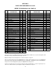
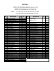
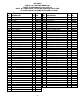
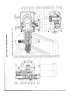
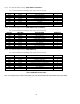
PARTS FOR PUMP MODELS 620 & 625
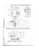
(REFER TO DRAWING NO. 6200, PAGE 20)
FIG.
NO.
DESCRIPTION QTY.
PART
NO.
FIG.
NO.
DESCRIPTION QTY.
PART
NO.
0101 Gearbox 1 000349 0140 Indicator Scale 1 100307
0102 Worm Gear 58 SPM 1 000350 0141 Screw 5/16-18 x 1-1/4'' LG 6 100205
Worm Gear 117 SPM 1 000351 0142 Set Screw 1/4-20 x 3/8'' LG 1 100308
0104 Eccentric 1 000352 0143 Screw #10-32 x 3/8'' LG 2 100309
0105 Connecting Rod 1 000353 0144 Screw 1/4-20 x 4 100211
0106 Eccentric Collar 1 000354 0145 Relief Valve Spring 1 100310
0107 Gear Shaft 1 000355 0146 "O"Ring, Relief Valve Cap 1 100200
0108 Gear Shaft Retainer 1 000356 2301 Pump Body 1 000380
0109 Thrust Washer 1 000357 2302 Pump Head 1 000382
0111 Worm 58 SPM 1 100291 2305 Piston 1 000384
Worm 117 SPM 1 100292 2306 Control Rod 1 000385
0113 Bearing Retainer 1 000358 2307 Sealing Plate 1 000386
0114 Connecting Rod Sleeve 1 000359 2308 Control Rod Screw 1 000377
0115 Sealing Nut 1 000360 2309 Pump Body Side, Backup Plater 1 000387
0116 Sealing Nut Retainer 1 000361 2310 Telfon Diaphragm 1 000388
0117 Control Knob 1 000362 2311 Relief Valve Ball Guide 1 000389
0118 Indicator Plate 1 000363 2312 Discharge Cap 1 000390
0119 Relief Valve Adjusting Screw 1 000364 2314 Vent Plug 1 000392
0120 Relief Valve Cap 1 000365 2318 Anti-Siphon Spring 1 100320
0121 Screw 1/4-20 x 1'' LG 3 100293 2328 Suction Cap 1 000404
0122 Dowel Pin 3/8'' x 1-1/2'' LG 3 100294 2330 Pump Head Backup Plate 1 000406
0123 Spring Pin 1/4'' x 1-2/4'' LG 1 100295 2332 1/8'' Pipe Plug 1 100196
0124 Screw 1/4-20 x 5/8'' LG 4 100211 2333 "O"Ring, Sealing Plate 1 100322
0125 Upper Bearing Cup 1 100296 2334 "O"Ring, Control Rod 1 100323
0126 Upper Bearing Cone 1 100297 2335 3/8'' Dia. Ball 1 100201
0127 Lower Bearing Cup 1 100298 2336 Screw 1/4-20 x 3/4'' LG 8 100329
0128 Lower Bearing Cone 1 100299 2337 "O"Ring, Vent Plug 1 100325
0129 Fill Plug Dipstick 1 000366 2338 Screw 5/8-11 x 4'' LG 2 100337
0130 1/2'' Pipe Plug 1 100300 2340 5/8'' Dia. Ball 4 100078
0131 Motoe Coupling 1 100098 2342 "O"Ring, Valve Seat 4 100327
0132 Motor Coupling Key 1 100218 2343 "O"Ring, Valve Cap 2 100328
0133 Screw 1/4-20 x 5/8'' LG 4 100211 2344 Screw 5/8-11 x 2'' LG 8 100343
0135 Oil Seal 1 100303 2361 Stack Spacer 1 002833
0136 Dowel Pin 5/8'' x 2'' LG 1 100304 2362 Ball Guide 3 002154
0137 Sprin
g
Pin 1/8'' x 3/4'' LG 1 100305 2363 Valve Seat 4 001432
0138 3/8'' Lock Washer 4 100217
0139 Screw 3/8-16 x 1'' LG 4 100216
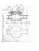
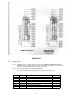
Valve stacks for the Series 620/625 pumps have been improved by the addition of close tolerance ball guides, which
allow better accuracy and better valve life at higher pressures.
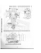
Original and improved stack arrangements are shown in the figures on page 27.
Parts are currently furnished only for the improved version. When ordering replacement sears for an original valve
stack design, order the ball guides (FIG. #2362) and spacer (FIG. #2361). Installing these parts and discarding the
old spacers and seats will upgrade the pump to the improved valve arrangement.
If seats are not replaced, it is not necessary to change the spacers and ball guides. If seats are replaced (the new
seats are of a different thickness) the ball guides and spacers must also be replaced.
19