for NEPTUNE SERIES 600 “dia-PUMP” MODELS 610 thru 647 NEPTUNE CHEMICAL PUMP CO., INC. Lansdale, PA. 19446 * Tel.
WARNING LOCKOUTS ARE REQUIRED BEFORE SERVICING THIS EQUIPMENT. SAFETY INSTRUCTIONS: Shut off/ Lockout pump Power before Servicing. Be certain pump isolation valves are closed – chemical is shut off. Bleed pressure before servicing.
TABLE OF CONTENTS SECTION I PARAGRAPH -- II -1.0 2.0 3.0 4.0 GENERAL DESCRIPTION LIMITED WARRANTY PARTS ORDERING INSTRUCTIONS 5.0 6.0 INSTALLATION INSTRUCTIONS GENERAL SUCTION PIPING DISCHARGE PIPING ADJUSTMENT OF INTERNAL RELIEF VALVE INSTALLATION OUTDOORS START UP PROCEDURE III -7.0 NORMAL MAINTENANCE MAINTENANCE IV 8.0 MOTOR OPERATING CONDITIONS V -- VI PAGE 1 2 3 4 4 5 6 6 8 8 9-12 9-12 13 TROUBLE SHOOTING CHART 14-16 9.0 10.
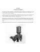
SECTION I GENERAL DESCRIPTION The Neptune series 600 “dia-PUMP” is a reliable metering pump of the high-pressure diaphragm type. Under constant conditions of temperature, pressure, and capacity adjustment settings, a plus or minus range of 1% metered discharge volume is maintained. A plunger reciprocating at a fixed stroke displaces hydraulic fluid which actuates a flexible, chemically inert, Teflon®, diaphragm to create pumping action.
SECTION I NEPTUNE CHEMICAL PUMP COMPANY LIMITED WARRANTY All Neptune Pumps are tested at the factory prior to shipment. Each part used in their construction has been carefully checked for workmanship. If the pump is installed properly, Neptune Chemical Pump Company, Inc.
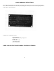
PARTS ORDERING INSTRUCTIONS The complete model number and serial number of the pump must be furnished to insure prompt and accurate parts service. These numbers are found on the name plate (sample photo below) located on the side of the pump. Refer to Section VI for complete parts lists. Send all orders or inquired for parts to: Parts Department Neptune Chemical Pump Company, Inc. P.O. Box 247 Lansdale, PA 19446 Tel: 215-699-8700 Fax: 215-699-0370 NOTE! PLEASE SUPPLY BOTH MODEL AND SERIAL NUMBERS.
SECTION II INSTALLATION INSTRUCTIONS 1.0 GENERAL 1.0.1 UNPACKING & INSPECTION When unpacking a pump or chemical feed system, be certain that no parts are thrown away. Examine the equipment for possible damage. If damage has occurred, file claim with the common carrier within 24 hours. Neptune will assist in estimating the repair costs. 1.0.2 The “dia-Pump” should be located on a level surface. Four mounting holes are provided to anchor the pump securely to the mounting surface.
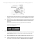
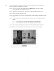
Please note Figure 1, indicating the correct rotation. Operation with the incorrect rotation will damage the pump and motor. 1.0.8 Please note, that some items in the parts list have more than one part number for an individual figure number. These different part numbers insure unique identification of parts, which are available in more than one material of construction, or as in the case of gears, more than one speed. Please use the part number, not the figure number when ordering. 1.0.
3.0 DISCHARGE PIPING 3.0.1 It is recommended that the “dia-PUMP” operate against a minimum discharge pressure of 50 psig. 3.0.2 All Neptune Series 600 “dia-Pumps” are supplied with an internally pre-set relief valve. This relief valve is set approximately 25% above the actual rated discharge pressure of the pump and is designed to protect the pump should a discharge pressure beyond the rated limit of the pump occur. 3.0.
4.0.2 To reset the relief valve to a higher pressure (the relief valve setting cannot be reduced because of design considerations), instructions are as follows: 4.0.21 Connect a test set-up shown in Figure IV below. NOTE: All parts must have a working pressure rating above the required set pressure. 4.0.22 Start and run the pump until air is relieved from the discharge liquid (hand valve open). 4.0.23 Remove relief valve cap (FIG. #0120). 4.0.
5.0 INSTALLATION OUTDOORS The “dia-PUMP” is a totally enclosed pump which can be used outdoors or indoors. When installed outdoors, make sure that the pump is protected against extremes of nature as follows: 5.0.1 Running of the pump when exposed to tropical sunshine with ambient temperature above 90° F (32°C) would cause excessive oil motor temperatures. The pump should be shaded and located in such a way as to permit an ample degree of air circulation. 5.0.
SECTION III PUMP MODELS 610 AND 615 NORMAL MAINTENANCE 7.0 MAINTENANCE Under normal conditions, the “dia-PUMP” should not require any significant amount of maintenance. It is advised that periodic visual observations be made of the oil level to made sure that it is within ¼” of the dipstick mark. The liquid end of the pump should also be inspected for leakage. These observations should be made regularly. The hydraulic fluid should be drained and replaced twice a year, using the drain plug (FIG.
SECTION III PUMP MODELS 620 AND 625 NORMAL MAINTENANCE 7.1 MAINTENANCE Under normal conditions, the “dia-Pump” should not require any significant amount of maintenance. It is advised that periodic visual observations be made of the oil level to make sure that it is within ¼” of the dipstick mark. The liquid end of the pump should also be inspected for leakage. These observations should be made regularly. The hydraulic fluid should be drained and replaced twice a year, using the drain plug (FIG.
SECTION III PUMP MODELS 635, 637 AND 647 NORMAL MAINTENANCE TO VIEW FIGURE NUMBERS: For Models 635 & 637 refer to Drawing on page 22. For Model 647 refer to Drawing on page 24. 7.2 MAINTENANCE Under normal conditions, the “dia-Pump” should not require any significant amount of maintenance. It is advised that periodic visual observations be made of the oil level to make sure that it is within ¼” of the dipstick mark. The liquid end of the pump should also be inspected for leakage.
7.4.1 7.3.13 Remove control rod assembly with control rod attached (FIG. #0117 for all pumps; #1406 and #1408 for Models 610 &615, #2306 and #2308 for Models 620 & 625, #3206 and #3208 for Models 635, 637 & 647) by turning counter clockwise until threads are disengaged, then pulling out. 7.3.14 Remove four sealing nut retaining screws (FIG. #0144). 7.3.15 Remove seal plate retainer (FIG. #0166) and sealing nut (FIG. #0115). 7.3.16 Remove seal plate (FIG.
SECTION IV MOTOR OPERATING CONDITIONS 8.0 The normal temperature rise for standard motors is 40° C above ambient temperature and, thus, it might appear that the motor is operating at a higher than normal temperature. This situation is normal and should not cause concern. As a precaution against motor overheating, it is recommended that the pump be located where adequate ventilation is available.
SECTION V TROUBLE SHOOTING CHART SYMPTOM 1. Pump Motor Will Not Operate. 2. Pump Does Not Deliver Rated Capacity. CAUSE REMEDY A. Blown Fuse. Check for short circuit B. Open thermal overload device in starter Reset. C. Low liquid level in tank (where low level cut-off is used). Fill Tank. D. Broken Wire Locate and repair. E. Low voltage Check for too light wiring. F. Oil “frozen” in pump. Thaw out. A. Starved suction. Replace suction piping with larger size. B. Leaky suction piping.
SYMPTOM 3. Pump delivers erratically. 4. Motor overheats thermal overload activates. 5. Noisy Operation. CAUSE REMEDY I. Low discharge pressure. A minimum discharge pressure of 50 psi is required to insure proper capacity control. A. Leaky suction line. Repair or replace piping. B. Worn or dirty valves or seats, or both. Clean or replace valve assembly. C. Excessive excursion of ball valves from seats (indicated by ball chatter). Increase back pressure. D.
SECTION VI PARTS LIST FOR PUMP MODELS 610 & 615 (REFER TO DRAWING NO. 6100, PAGE 18) FIG NO.
18
SECTION VI PARTS FOR PUMP MODELS 620 & 625 (REFER TO DRAWING NO. 6200, PAGE 20) FIG. PART NO. NO. DESCRIPTION QTY.
SECTION VI PARTS LIST FOR PUMP MODELS 630, 635 & 637 (REFER TO DRAWING NO. 6300, PAGE 22) NOTE: N-3 PUMPS HAVE 316SS PUMP HEAD AND 316SS TRIM. N-4 PUMPS HAVE C-20 PUMP HEAD AND C-20 TRIM. FIG. NO.
SECTION VI PARTS LIST FOR PUMP MODEL 647 (REFER TO DRAWING NO. 6347, PAGE 24) NOTE: N-3 PUMPS HAVE 316SS PUMP HEAD AND 316SS TRIM. N-4 PUMPS HAVE C-20 PUMP HEAED AND C-20 TRIM. FIG NO.
APPENDUM 600 SERIES PVC PUMP THEORY OF OPERATION The NEPTUNE 600 PVC “dia-Pump” is a double diaphragm pump employing the basic drive unit of the Neptune series 600 “dia-Pump”. All drive, stroke control parts and oil head are common to the original flat diaphragm models. An intermediate plate and all parts in the liquid side are different from the basic pump. Hydraulic oil displaces a flat diaphragm, which displaces “an intermediate fluid” which, in turn, flexes the second flat diaphragm. Note: 1.
SECTION VI 10.0 SPARE PARTS 10.0.1 10.0.2 Important – When ordering spare parts, please show MODEL NUMBER AND SERIAL NUMBER of pump for which parts are being ordered. This information can be found on a stainless steel nameplate riveted to the side of the pump. Recommended Spare Parts for PUMP MODELS It is recommended that the following parts be kept in stock for a pump: FIG. NO. PART NO.
10.0.3 Recommended Spare Parts for PUMP MODELS 620 AND 625 It is recommended that the following parts be kept in stock for a pump: FIG. NO. PART NO/ DESCRIPTION QUANTITY 2310 2363 2333 2334 2337 2340 2342 2343 000388 001432 100322 100323 100325 100078 100327 100328 Teflon Diaphragm Valve Seat Sealing Plate “O” Ring Control Rod “O” Ring Vent Plug “O” Ring Valve Ball Valve Seat “O” Ring Discharge & Suction Cap “O” Ring 1 4 2 2 2 4 8 4 10.0.
SECTION VII SPECIAL INSTRUCTIONS FOR SERIES 600 ‘DIA-PUMPS” WITH PNEUMATIC STROKE CONTROL Refer to Drawing No. B-001743 11.0 FUNCTION OF THE PNEUMATIC STROKE CONTROL UNIT. The Neptune pneumatic stroke control unit controls the capacity of the “dia-PUMP’ over the full operating range.
11.0 PARTS UNIQUE TO PUMPS SUPPLIED WITH NEPTUNE PNEUMATIC STROKE CONTROL. (Refer to Drawing B-001743). PART NO.
31
32