
Manual

26
APPENDIX
THE FOLLOWING CHANGES IN TEXT MUST BE CONSIDERED WHEN USING THIS
MANUAL FOR THE SERIES 500-A “dia-PUMP”. EXCEPT FOR THE DIFFERENCES LISTED
BELOW, THIS INSTRUCTION MANUAL APPLIES COMPLETELY TO BOTH THE SERIES 500
AND SERIES 500-A “dia-PUMP”.
PAGE SECTION PARAGRAPH
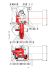
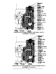
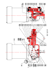
7 4.0.1 2 Drawing number 5024 illustrates the location of the
internal relief valve (FIG. #527 thru #530).
7 4.0.21 Location of 500-A “dia-PUMP” Internal Relief Valve is on
top of the Pump Body, not as shown in Figure IV.
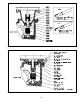
13 15.0.3 Remove retaining bolts … (FIG. #5016, 5018, 5019,
5020)
13 15.0.4 Turn Case …(FIG. #5016, 5018, 5019, 5020)
13 15.0.5 To replace motor … (FIG. #5016, 5018, 5019, 5020)
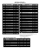
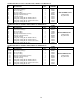
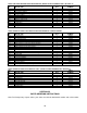
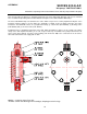
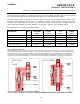
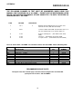
Parts for Series 500-A “dia-PUMP” not common to Series 500 “dia-PUMP”. Refer to Drawing 5024
FIG.
NO.
DESCRIPTION
QTY.
PART
NUMBER
5002 Shaft Retainer Assembly 1 000242
5003 Gear Shaft 1 100251
5005 Worm Gear 37 SPM 1 000292
5006 Worm Gear 72 SPM 1 000293
5007 Worm Gear 117 SPM 1 000291
5008 Worm Gear 175 SPM 1 000294
5016 Gear Box (Model 500 Only) 1 000288
5018 Gear Box (Model 510/515 Only) 1 000282
5019 Gear Box (Model 520/522/525 Only) 1 000283
5020 Gear Box (Model 530/532/535/538 Only) 1 000284
RECOMMENDED SPARE PARTS
The Spare Parts Kits listed on page 19 of this manual comprise the recommended
spare parts for all Series 500 dia-PUMPS.
SERIES 500-
A