OPERATING & INSTRUCTION MANUAL NEPTUNE SERIES 500 PUMPS MODEL 481 THRU 547 500-A, 500-D, 500-E, 500-S and 500-VS Types NEPTUNE MEMBER OF TM A A COMPANY COMPANY 204, Dekalb Pike, Lansdale, PA 19446 P U MP S OL U T I ON S GR OU P A DOVER COMPANY Tel.
WARNING LOCKOUTS ARE REQUIRED BEFORE SERVICING THIS EQUIPMENT. SAFETY INSTRUCTIONS: Shut off/Lockout pump Power before Servicing. Be certain pump isolation valves are Closed and chemical is shut off. Bleed pressure before servicing.
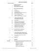
TABLE OF CONTENTS SECTION PARAGRAPH PAGE I — GENERAL DESCRIPTION LIMITED WARRANTY PARTS ODERING INSTRUCTIONS 1 2 3 II — INSTALLATION INSTRUCTIONS 4 1.0 2.0 3.0 4.0 5.0 6.0 7.0 8.0 III — 9.0 10.0 11.0 12.0 13.0 GENERAL SUCTION PIPING DISCHARGE PIPING ADJUSTMENT OF INTERNAL RELIEF VALVE INSTALLATION OUTDOORS START-UP, FLOODED SUCTION START-UP, SUCTION LIFT START-UP, AFTER SUCTION HAS RUN DRY 4 5 6 6 8 8 9 9 NORMAL MAINTENANCE AND DISASSEMBLY INSTRUCTIONS 10 10 10 10 10 11 15.
SECTION I GENERAL DESCRIPTION The Neptune Series 500 “dia-PUMP” is a reliable metering pump of the high-pressure diaphragm type. Under constant conditions of temperature, pressure, and capacity adjustment settings, a +/- 1% metered discharge volume is maintained. A plunger reciprocating at a fixed stroke displaces hydraulic fluid, which actuates a flexible, chemically inert, Teflon® diaphragm to create pumping action.
SECTION I NEPTUNE CHEMICAL PUMP COMPANY LIMITED WARRANTY All Neptune Pumps are tested at the factory prior to shipment. Each part used in their construction has been carefully checked for workmanship. If the pump is installed properly, Neptune Chemical Pump Company, Inc. warrants to the purchaser of this product for a period of three years from the date of shipment, this product shall be free of defects in material and/or workmanship, as follows: 1. Neptune Chemical Pump Company, Inc.
PARTS ORDERING INSTRUCTIONS The complete model number and serial number of the pump must be furnished to insure prompt and accurate parts service. These numbers are found on the name plate (sample below) located on the side of the pump. Refer to Section VII for complete parts lists. www.neptune1.com A DOVER COMPANY CHEMICAL PUMP CO. LANSDALE, PA 19446 TEL: 215-699-8700 Send all orders or inquiries for parts to: Parts Department Neptune Chemical Pump Company, Inc. P.O. Box 247 Lansdale, PA 19446 Tel.
SECTION II INSTALLATION INSTRUCTIONS 1.0 GENERAL 1.0.1 When unpacking a pump or chemical feed system, be certain that no parts are thrown away. Examine the equipment for possible damage. If damage has occurred, file claim with the common carrier within 24 hours. Neptune will assist in estimating the repair costs. 1.0.2 The ‘‘dia-Pump’’ should be located so as to avoid an ambient temperature above 120°F, 50°C. Free air circulation is important when considering the location of the pump. 1.0.
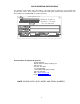
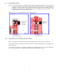
OIL LEVEL.DWG FIGURE 1 FIGURE 1A 1.0.11 Set capacity knob to zero and remove Air Bleed Plug from the top of Oil Chamber, refer to drawings HP-1102 (page 21) for Series 500 and drawing 5024 (page 27) for Series 500-A and 500-E for location of plug. Fill gear box and pump by pouring the hydraulic fluid supplied through the fill opening at the rear of the pump. Pour fluid in slowly until it has reached the correct level per Figure 1A. Do not over fill as this can cause damage to the motor.
3.0 DISCHARGE PIPING 3.0.1 It is recommended that the ‘‘dia-Pump’’ operate against a minimum discharge pressure of 50 psig. A back pressure spring is supplied loose with the pump. If 50 psig back pressure is not provided by the application, the back pressure spring should be installed on the pin under the discharge valve cap. Installation of the back pressure spring artificially creates a discharge head. (Refer to Figures II and III.) Note: Spring is not provided in 500-E Series. 3.0.
4.0.1 (Continued) To protect the external piping system, it is recommended that a relief valve as manufactured by Neptune Chemical Pump Company, or equal, be placed in the discharge line of the pump. It is further recommended that this relief valve be piped into return of the tank with clear PVC tubing so that it can be determined if the solution is by-passing through the valve and returning to the tank, indicating a line blockage.
4.0.3 Parts required to test or adjust Relief Valve Pressure. 1 Pc. 2 Pcs. 1 Pc. 2 Pcs. 1 Pc. 1 Pc. 1 Pc. 1 Pc. 1 Pc. 1/2” Pipe Nipple 6” Long 1/2” Pipe Nipple 2” Long 1/2” Hand Valve 1/2” Tee 1/2” NPT X 1/2” Hose (Fitting) 1/2” Hose, As Required 1/2” Pressure Gauge (Minimum Gauge Pressure 500 psi) Allen Wrench 3/16” External Relief Valve (optional) NOTE The above parts must have a working pressure rating above the required set pressure. 5.
4. On initial gearbox fill or after replacing hydraulic fluid, run pump for one-half to one hour to warm up oil and allow air bubbles to dissipate. Check discharge line for indication of flow. 5. Once discharge flow is observed proceed to paragraph number 6; if no flow, repeat steps 3 and 4. 6. Increase capacity adjustment setting to 70% of maximum capacity and operate for 10-20 minutes. 7.
SECTION III NORMAL MAINTENANCE AND DISASSEMBLY INSTRUCTIONS 9.0 MAINTENANCE Under normal conditions, the “dia-Pump”does not require any significant amount of maintenance. It is advised that periodic visual observations be made of the oil level. See Page 5 for correct oil level. The liquid end of the pump should also be inspected for leakage. These observations should be made regularly, at least every 48 hours. 10.
12.0 REPLACING OF VALVE CARTRIDGES (Continued) FIGURE V CUT-AWAY VIEW OF VALVE SECTION, METAL HEAD PUMP FIGURE VI VALVE CARTRIDGE REMOVAL, METAL HEAD PUMP FIGURE VII VALVE CARTRIDGE REMOVAL, PVC HEAD PUMP 13.0 PROCEDURE FOR REPLACING CONTROL ROD “O” RING (fig. #517) AND SEALING PLATE “O” RING (FIG.#516). Refer to Figure VIII 1. Remove Drain Plug (FIG. #510) and drain hydraulic fluid. 2. Remove Indicator Plate (FIG. #520) by removing two holding screws. 3.
5. Replace Control Rod “O” Ring (FIG. #517) and Sealing Plate “O” Ring (FIG. #516). 6. Take care when replacing Sealing Plate, (FIG. #518) so as to not damage the Sealing Plate “O” Ring (FIG. #516). 7. Replace all parts and fill pump with hydraulic fluid per previous instructions. 8. Follow start-up procedure as if starting a new pump. FIGURE VIII REMOVAL OF CONTROL ROD ASSEMBLY 14.0 REMOVAL OF PUMP HEAD AND REPLACEMENT OF DIAPHRAGM (REFER TO FIGURES IX AND X) 14.0.1 Remove Drain Plug (FIG.
14.0 REMOVAL OF PUMP HEAD AND REPLACEMENT OF DIAPHRAGM (Continued) FIGURE IX 15.0 FIGURE X REMOVAL OF MOTOR FROM STANDARD “dia-PUMP” (REFER TO FIGURE XI) 15.0.1 Disconnect all wires leading to the motor. 15.0.2 Remove Drain Plug (FIG. #510) and drain hydraulic fluid from pump. 15.0.3 Remove the fan cover and fan if the motor is a TEFC type. Remove retaining bolts from the top of the motor. These bolts are threaded directly into the Pump Gear Box (FIG. #500). 15.0.
SECTION IV MOTOR OPERATING CONDITIONS 16.0 The Standard Series 500 “dia-Pump” is supplied with a 1/3 HP or 1/2 HP/single phase/totally enclosed fan cooled motor as an integral part of the pump itself. The normal temperature rise for this motor is 40ºC above ambient temperature and thus, it might appear that the motor is operating at a higher than normal temperature. This situation is normal and should not cause concern.
SECTION V TROUBLE SHOOTING CHART SYMPTOMS CAUSES REMEDIES 1. Pump Motor Will Not Operate. A. Blown Fuse. A. Check for short circuit or overload. B. Open thermal overload device in starter or motor. B. Reset. C. Low liquid level in tank (where low level cut-off is used). C. Fill tank. D. Broken wire. D. Locate and repair. E. Low voltage. E. Check for too light wiring. F. Oil “frozen” in pump. F. Thaw out. A. Starved suction. A.
SYMPTOMS *3. Pump delivers erratically. CAUSES REMEDIES L. No foot valve strainer. L. Install one. A. Leaky suction line. A. Repair or replace piping. B. Worn or dirty valves or seats, or both. B. Clean or replace cartridges. C. Excessive excursion of ball from valve seats (indicated by ball chatter). D. Liquid too close to boiling point. E. Leaky internal or external relief valve. C. Replace cartridges. D. Reduce temperature or raise suction pressure. E. Repair or replace relief valve. 4.
SECTION VI SEE ELECTRIC STROKE CONTROL INSTRUCTION MANUAL FOR PUMPS FURNISHED WITH OPTIONAL ELECTRIC STROKE CONTROL. SPECIAL INSTRUCTIONS FOR SERIES 500 “dia-Pumps” WITH PNEUMATIC STROKE CONTROL 17.0 FUNCTION OF THE PNEUMATIC STROKE CONTROL UNIT The Neptune pneumatic stroke control unit controls the capacity of the “dia-Pump” over the full operating range.
SECTION VII PARTS LIST SERIES 500 AND 500-A PUMP PARTS FIG. NO.
SPARE PARTS KIT (N1 AND N3 CONSTRUCTION) MODELS 500 THROUGH 547 FIG. PART NO. DESCRIPTION QTY.
PARTS FOR PUMPS WITH MOTOR FLANGE ADAPTER, (REFER TO PARTS DRAWING 000911 ON PAGE 25) FIG. PART NO. DESCRIPTION QTY.
Drawing HP-1102 21
SERIES 500 PVC HEAD ASSEMBLY WITH SMALL CAVITY (ASSEMBLY P/N 002074) SERIES 500 PVC HEAD ASSEMBLY WITH STANDARD CAVITY (ASSEMBLY P/N 002075) Kynar liquid end material code [N8] is available in the style used for Series 500-E only. See Page 27.
NEW OLD DRAWING #000911 DRAWING # FALP 23
SERIES 500-E-AR APPENDIX “dia-pump” INSTRUCTIONS Addendum to Operating and Instruction Manual for the 500 dia-pump and 500-A dia-pump This sheet describes the differences in liquid head design of the Series 500-E-AR “dia-pump”. This sheet is intended to be used with the Operating and Instruction Manual for Neptune Series 500 and 500-A “Dia-Pumps”. The Series 500-E-AR Pumps are identical to the Series 500-A except for an economy liquid head.
SERIES 500-E APPENDIX “dia-pump” INSTRUCTIONS Addendum to Operating and Instruction Manual for the 500 dia-pump and 500-A dia-pump This sheet describes the differences in liquid head design of the Series 500-E “dia-pump”. This sheet is intended to be used with the Operating and Instruction Manual for Neptune Series 500 and 500-A “Dia-Pumps”. The Series 500-E Pumps are identical to the Series 500-A except for an economy liquid head.
APPENDIX SERIES 500-A THE FOLLOWING CHANGES IN TEXT MUST BE CONSIDERED WHEN USING THIS MANUAL FOR THE SERIES 500-A “dia-PUMP”. EXCEPT FOR THE DIFFERENCES LISTED BELOW, THIS INSTRUCTION MANUAL APPLIES COMPLETELY TO BOTH THE SERIES 500 AND SERIES 500-A “dia-PUMP”. PAGE SECTION PARAGRAPH 7 4.0.1 2 7 4.0.21 Location of 500-A “dia-PUMP” Internal Relief Valve is on top of the Pump Body, not as shown in Figure IV. 13 15.0.3 13 13 15.0.4 15.0.5 Remove retaining bolts … (FIG.
27 Drawing 5024
APPENDIX SERIES 500-VS HIGH VISCOSITY INTRODUCTION The Neptune Series 500 “dia-Pump” is available with a special liquid end to handle higher viscosity liquids. Model numbers of pumps are for example 515-VS-N3 or 535-VS-N3. This liquid end, which is only available in 316SS, is different than the standard liquid end as the suction valve, back up plate, and liquid head are modified to allow oversized porting to enable thick liquids to be drawn into the pump on the suction stroke.
MODEL 481 APPENDIX LOW VOLUME PUMP INTRODUCTION A special version of the Neptune Series 500 Pump is the Model 481. This pump is different than the standard pump due to the unique Low-Flow design, which involves a smaller Piston and Metering Device with extremely close tolerances. (Correct installation is critical for proper pump operation.) The valves used in this pump also contain smaller ball checks and seats. Refer to Parts Drawing S00091 for cross-sectional details.
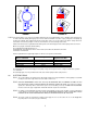
30 SEALING PLATE, O-RING P/N 105079 CONTROL ROD, O-RING P/N 106997 BACKUP PLATE, OIL SIDE P/N 003380 PUMP HEAD P/N 003391 DRAWING S00091 MODEL 481 LOW VOLUME PUMP SEALING PLATE P/N 003389 PUMP CYLINDER, RIGHT HAND P/N 003475 CONTROL ROD, 5/32" DIA. P/N 003388 PISTON, 5/16" DIA.
APPENDIX DOUBLE DIAPHRAGM OPTION ADDENDUM: Special instructions for Series 500, 500-A & 560 “dia-Pumps” with Double Diaphragm THEORY OF OPERATION The instructions below are for Neptune’s optional Double Diaphragm Kit which is available for the Neptune Series 500, 500-A, and 560 “dia-Pumps”. Use of a double diaphragm allows diaphragm to be monitored and provides an early warning upon failure of either diaphragm allowing repairs to be made before process fluid mix with the pump hydraulic fluid.
DOUBLE DIAPHRAGM OPTION APPENDIX ADDENDUM: Special instructions for Series 500, 500-A & 560 “dia-Pumps” with Double Diaphragm 1.0.8 Close valve Item No. 5 1.0.9 Remove the vacuum pump. Plug valve Item No. 5 with a 316SS pipe plug Item No. 12 1.0.10 Reinstall the Pump 1.0.11 Follow procedure in Neptune Standard Operating and Instruction Manual for Initial Pump Startup ® ® NOTE: Neptune furnishes a Mityvac vacuum pump from Mityvac No.
MATERIAL SAFETY DATA SHEET Page 1 of 4 1. CHEMICAL PRODUCT AND COMPANY IDENTIFICATION Product Name: EP 68 Gear Oil Product Code: Generic Name: Heavy-duty, Multi-grade Gear Oil Chemical Family: Petroleum Hydrocarbons & Additives Manufacturer: Scot Lubricants 1801 E. Tremont Street P.O. Box 326 Allentown, PA 18105 2.
EP 68 Gear Oil Page 2 of 4 6. ACCIDENTAL RELEASE MEASURES SPILLS OR LEAKS: Contain spills, advise EPA, state agency, if required. Absorb on inert material, shovel, sweep, or vacuum spill. 7. HANDLING AND STORAGE NFPA Class IIIB Storage. Wash thoroughly after handling. 8. EXPOSURE CONTROLS/PERSONAL PROTECTION VENTILATION: Ventilate as needed to comply with exposure limit. General Dilution ventilation acceptable.
EP 68 Gear Oil Page 3 of 4 11. TOXICOLOGICAL INFORMATION – cont’d SEVERELY SOLVENT REFINED HEAVY PARAFFINIC PETROLEUM OIL: INHALATION: Low acute toxicity. SKIN: Practically non-toxic if absorbed; may cause moderate irritation with prolonged and repeated contact. EYE: Minimally irritating on contact. INGESTION: Practically non-toxic if swallowed. CALCIUM SULFONATE: INHALATION/INGESTION: No data available. SKIN: Moderate irritant. Cause allergic skin reaction in animals. EYE: Moderate to severe irritation.
EP 68 Gear Oil Page 4 of 4 15. REGULATORY INFORMATION TSCA: This material complies with the TOXIC SUBSTANCES CONTROL ACT (15 USC 2601-2629) and is listed in the TSCA Inventory.
MATERIAL SAFETY DATA SHEET Page 1 of 4 3. CHEMICAL PRODUCT AND COMPANY IDENTIFICATION Product Name: EP 90 Gear Oil Product Code: Generic Name: Heavy-duty, Multi-grade Gear Oil Chemical Family: Petroleum Hydrocarbons & Additives Manufacturer: Scot Lubricants 1801 E. Tremont Street P.O. Box 326 Allentown, PA 18105 4.
EP 90 Gear Oil Page 2 of 4 6. ACCIDENTAL RELEASE MEASURES SPILLS OR LEAKS: Contain spills, advise EPA, state agency, if required. Absorb on inert material, shovel, sweep, or vacuum spill. 7. HANDLING AND STORAGE NFPA Class IIIB Storage. Wash thoroughly after handling. 8. EXPOSURE CONTROLS/PERSONAL PROTECTION VENTILATION: Ventilate as needed to comply with exposure limit. General Dilution ventilation acceptable.
EP 90 Gear Oil Page 3 of 4 11. TOXICOLOGICAL INFORMATION – cont’d SEVERELY SOLVENT REFINED HEAVY PARAFFINIC PETROLEUM OIL: INHALATION: Low acute toxicity. SKIN: Practically non-toxic if absorbed; may cause moderate irritation with prolonged and repeated contact. EYE: Minimally irritating on contact. INGESTION: Practically non-toxic if swallowed. CALCIUM SULFONATE: INHALATION/INGESTION: No data available. SKIN: Moderate irritant. Cause allergic skin reaction in animals. EYE: Moderate to severe irritation.
EP 90 Gear Oil Page 4 of 4 15. REGULATORY INFORMATION TSCA: This material complies with the TOXIC SUBSTANCES CONTROL ACT (15 USC 2601-2629) and is listed in the TSCA Inventory.
MAINTENANCE LOG Pump Model___________________________ Serial #_______________________________ Strokes Per Minute______________________ Maximum Flow________________________ Piston Diameter________________________ Maximum Pressure_____________________ Spare Parts Kit #____________________________________________________________ NEPTUNE CHEMICAL PUMP CO., INC. Tel.