2N ® GSM ISDN GATEWAY Lite User’s Manual Version: 1.
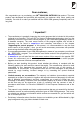
Dear customer, We congratulate you on purchasing your 2N ® GSM ISDN GATEWAY Lite product. This new product was developed and produced with emphasis on maximum utility value, quality and reliability. Our wish is to make you satisfied with the ISDN GSM gateway completely and for a long time. ! Important ! • • • The manufacturer is gradually improving the control program that is included in this product (referred to as firmware).
Packing list Parts that make up the 2N ® GSM ISDN GATEWAY Lite product and its accessories correspond to the following list: Item Quantity GSM gateway – model corresponding to the ordering no.
CONTENTS 1. I N T R O D U C T I O N .......................................................................................... 4 1.1. 1.2. 1.3. 1.4. PURPOSE ........................................................................................................................................ 4 HOW TO SAVE TELEPHONE FEES ...................................................................................................... 4 OTHER BENEFITS AND POSSIBILITIES OF USE............................................
1. Introduction 1.1. Purpose • • • • • 2N ® GSM ISDN GATEWAY Lite is mainly designed to be connected to any ISDN PBX. It enables direct calling to the GSM network. It can also be used in connection with an ISDN phone set, with a phone set via a terminal adapter, with a coin payphone via a terminal adapter, etc. Its basic function is the voice mode, i.e. outgoing or incoming calls. The gateway is equipped with all functions necessary for this use and it provides maximum comfort in this mode.
1.3. Other benefits and possibilities of use • • • While phoning you are not exposed to a direct impact of a high-frequency electromagnetic field as in the case of a mobile phone. You can also connect a coin payphone via a terminal adapter – the ISDN GSM gateway can send tariff impulses. You may determine the price for various kinds of connection yourselves (with a profit). You can use the ISDN GSM gateway in your company network together with the MobilChange application 1.4.
® 2. Getting to know 2N GSM ISDN GATEWAY Lite Reset button SIM card holder 2 Wall mounting bracket Connector for GSM 2 antenna SIM card holder 1 Connector for GSM 1 antenna TE1 NT1 RS232 connector Power connector Fig.
2.1. Quick installation • Correct position - 2N ® GSM ISDN GATEWAY Lite is designed for a vertical surface Installation. Fix the bracket that is a part of the delivery to the wall and hang the gateway onto it. Recommended working position and other more detailed recommendations are described in chapter 3.1. • Connecting cables - Use ISDN cables to connect the gateway to your ISDN PBX (or other ISDN terminals). Connect the cables from your ISDN connection to the gateway.
® 3. Basic description of 2N GSM ISDN GATEWAY Lite installation 3.1. Correct positioning • 2N ® GSM ISDN GATEWAY Lite is designed to be installed on a vertical surface. The required working position is shown in fig. 2. • The ISDN GSM GATEWAY Lite may be operated in another working position (e.g. lying on a table) just temporarily – e.g. when being quickly tested during servicing. • The range of acceptable working temperatures and humidity is quoted in the “Technical parameters“ chapter.
3.2. Connecting an external antenna antenna Konektory antén Use the SMA antenna connector to connect either the entire antenna or the cable of an external antenna you have installed in a place with a good GSM signal. The antenna should be in a vertical position. The parameters of the antenna and cable are quoted in Technical parameters. Tighten the antenna connector lightly with your hand, do not use a wrench! For signal strength see 6.4.3.
Hang up. To enter PUK (use if you have confused three times or forgotten the PIN): Procedure Description of steps Pick up the earpiece, dial the service prefix (default ), dial or PUK PUK (PUK entering service). Press or to select GSM 1 or GSM 2 module. Enter the PUK. If it is shorter than eight digits, then press to quit Re-enter the PUK. Hang up. * Entering PIN and PUK codes you are guided by voice instructions.
3.4. Inserting SIM card into 2N ® - GSM ISDN GATEWAY Lite Insert SIM card Fig.4: Inserting SIM cards into the ISDN GSM gate Take the SIM holder out SIM card provider 1 SIM card provider 1 If you want to insert a SIM card, you should use a suitable object to press the yellow micro-button to push the drawer out. Take the drawer out, insert the SIM card and slide it back. You can insert a SIM card when the gate is switched on but have to reset the gate. Fig.
3.5. Power supply connection • Check whether the voltage in your mains corresponds to the data on the data plate on the product. • Use the supply adapter that is a part of your ISDN GSM GATEWAY Lite package. * • Check whether you have connected an antenna. If you connect power supply to the gateway without connecting an antenna, the GSM module transmitter might get damaged. • Plug the adapter connector in the gateway (see the lower front connectors – fig. 1).
13
3.7. Connecting NT and TE connectors The connection diagrams of NT or TE connector are shown in figs. 7 and 8. Individual connections may be selected in accordance with chapter 5 “Ways of connecting 2N ® GSM ISDN GATEWAY Lite“ while you should know the connection topology of your ISDN equipment, see chapter 4. The configuration of pins of RJ-45 connectors for TE and NT is shown in figs. 10 and 11. ISDN network NT ISDN net NT PBX Fig 8: Connection of connectors ISDN terminal Fig.
3.8. Signalling LED lamps 3.8.1. Charts – basic functions of LED lamps Fig.12: Signalling LED lamps Status of LED lamps for ISDN Each of the two lines of opposite direction (TE1/NT1 ; TE2/NT2) has a LED lamp of its own to indicate the status of B channels on the line. Status BRI ISDN Line Free 1. B-channel busy 2.
4. Possible connection topologies of your ISDN equipment 4.1. Point-to-Point (euroISDN with DDI) To be able to configure your ISDN GSM GATEWAY Lite you have to know the connections of your ISDN equipment. The first option is the Point-to-Point connection (euroISDN with DDI) as shown in fig. 13. You can recognise a line in the Point-to-Point configuration easily because there is no ISDN telephone, modem, etc. connected to it. Public phone net.
® 5. Ways of connecting 2N GSM ISDN GATEWAY Lite The ISDN GSM gateway is used to route calls from ISDN lines to GSM modules. The gateway can be connected as follows: • Gateway as NT ( simulates a network ) in configuration Point-to-Point and Point-to-Multipoint. • Gateway as TE ( simulates a phone) in configuration Point-to-Point and Point-to-Multipoint.
5.2. Connecting an ISDN telephone set to 2N ® GSM ISDN GATEWAY Lite The TE1 port are connected to the ISDN. If the network is not connected, the telephone must by supplied by an external supply adapter that simulates the voltage of the ISDN. The mains supply adapter that simulates the ISDN voltage may be ordered with its ordering no. 502000. GSM network Power adapter ISDN GSM gate ISDN terminals Fig.
5.3. Connecting 2N ® GSM ISDN GATEWAY Lite The 502081, 502083, 502085 models contain the following interfaces: 1 connector for a GSM module antenna 1 RJ45 TE/NT connector to connect NT1/TE1 1 RS232 serial interface connector to communicate with a PC. The 502082, 502084, 502086, 502088 models contain the following interfaces: 2 connectors for GSM module antennas 1 RJ45 TE connector to connect NT1 1 RJ45 NT connector to connect TE1 1 RS232 serial interface connector to communicate with a PC.
5.4. Connection of More ISDN Terminals to MSN ISDN Line Terminals (connected to the same NT, TE) must be connected using not-crossed fourwire connection cables. If you connect a remote ISDN terminal, attach a terminating circuit to the end, see fig. below. Fig 21: Correct MSN ISDN bus configuration ISDN, ISDN GSM gateway, ISDN tel., fax, ISDN terminal, terminating circuit socket Max. 8 devices ISDN ISDN síť činet PBX or PBX Socket with termination circuit. Max.
5.5. Outgoing call via GSM gateway connected to PBX Routing to a GSM network When a subscriber connected to the PBX lifts the phone and dials a number that is evaluated by the PBX as a “GSM gateway onset”, the list of restricted numbers is checked and if the same number is found the call is rejected. You may add an exception to prohibited destinations in the chart of authorised numbers. These numbers will be accepted even though they lie in a prohibited destination.
5.6. Incoming calls from GSM and ISDN Below, you will find points that an incoming call goes through. These points are listed in their real order. All these services can be authorised or prohibited selectively. 1. 2. CALLBACK When the function CALLBACK is activated and an incomming call has the same CLIP as CLIP for CALLBACK, the GSM gateway for defined time doesn’t receive this incomming call (the call is only ringing).
TE1,1-NT1,2-TE2,3-NT2). Quit with . Select validity in days (0- permanent validity, . maximum 250). Terminate with If you selected a higher number than 0 in the preceding step, select the mode: 1 - time in which the item is restored whenever this number is called; 0 – item will be deleted in the number of days selected in the validity step. Hang up. * Saving CLIP you are guided by voice instructions.
4. DISA If DISA is activated and a welcome message has been recorded, this message is played for every incoming call with the exception of calls listed in point 2 and there is a waiting time for the DTMF number. This timeout is listed in the general parameter chart as “Waiting time for the first number”.
5.7.2. Connection diagram GSM gateway 111 222 PBX 333 Description of a model situation: A customer is calling Mr. “Z” from a landline. PBX is set up to call also line 333 when calling line 222. Mr. “Z” is out of his office (business trip, lunch), the GSM gateway redirects the call to a defined mobile telephone number (Mr. “Z”’s mobile telephone). Mr. “Z” answers the call with his mobile phone and, after a few minutes, parks the call and calls 111 (e.g., secretary).
5.8. Recording DISA message The DISA message can be put in the gateway in two ways: 1. You can record the message in your PC and store the disa.vce file in the gateway (see 6.4.3). 2. You can record the message from an ISDN telephone. As regards the PBX, it depends on its programming. It must be connected to a port of the gateway and proceed in the same way as in the case of a phone.
6. Instructions to use ISDN GSM Lite program 6.1. Installing ISDN GSM Lite program The 2N ® GSM ISDN GATEWAY Lite package includes an installation CD that contains the installation of the ISDN GSM program. When you insert the CD or floppy disks into the drive of your PC the entire installation will be started. If your CD is not run automatically after being inserted (or you use installation diskettes), start installing by running the ISDN GSM program. Wait until the installation is completed.
6.3. Connecting 2N ® GSM ISDN GATEWAY Lite to your PC To set parameters you must first establish communication with the gateway after starting the program. To establish the communication correctly you should use the MENU “Setting > Communication“. The basic setting is shown in fig. 23. More detailed information see 6.4.4. To connect the gateway and establish mutual communication with your PC you should use the MENU “Gateway > Connect gateway“, or the icon “Connect gateway“ in the button bar: Fig.
6.4.1. File menu Fig. 24: File menu Using this menu you can work with the gateway configuration file config.cfg or firmware configuration file, i.e. read, store, etc. It also contains an item for finishing the program. Load – The configuration file “config.cfg“ that was last stored will be downloaded from the directory where the ISDN GSM program is stored. Or during the first run downloading the firm parameters will be requested.
6.4.2. Gateway menu This menu contains commands for connecting/disconnecting the gateway and a list of gateways for remote supervision. Fig.25: Gateway menu Connect gateway – connects the ISDN GSM gateway with your PC and establishes mutual communication via the RS232 serial interface. Note: The gateway must be connected and the communication must be correctly set in the “Setting > Communication” menu. Disconnect gateway – disconnects the gateway and interrupts the gateway-PC communication.
6.4.3. Gateway control menu It contains the following command items for the ISDN GSM Lite gateway: Diagnostics – information about GSM modules including charts showing how strong individual GSM signals are, information on SIM cards, free minutes for each GSM provider, PIN entering – you enter the PIN if you have a new SIM card with the PIN code active; you enter the PIN just once, the gateway will remember it; you can enter the PIN from your ISDN telephone too (see chapter 3.
1/ Get ready firmware file (Pmain.bin) in a pre-selected directory. 2/ Select Upload firmware, open the Pmain.bin file. 3/ The program now uploads your new firmware automatically – the gateway is reset several times during the process. Do not interrupt the procedure to avoid wrong uploading and gateway breakdown! Load trace – stores a record of the gateway operation and faults on a disk/in the current directory (the contents of this record can be selected in the “System Parameters > Trace“ menu).
6.4.5. Help menu This menu contains the ISDN GSM Lite program help, instructions to the help and details on the program version.
6.4.6. Button bar Fig.
6.5. Configuration As already mentioned, you will find the following card menus in the program: “Topics“ and “Alphabetical glossary“. These card menus contain duplicated items (as shown in figs. 29 and 30) and it is up to the user to decide which menu to choose to make editing parameters clear. In these parameters you can set the particular behaviour of the ISDN GSM gateway. 6.5.1. Topics and Alphabetical glossary Fig.29: Topics Fig.
6.5.2. ISDN Fig.31: Basic ISDN parameters 6.5.2.1 Basic parameters Connection type The type of connection depends on the equipment the gateway port is connected to. The parameter must be the same for all interconnected pieces of equipment. - Point-to-Multipoint is used to connect two to eight ISDN devices and it uses the MSN service (Multiple Subscriber Number). This type of connection is used for telephones and ISDN terminals.
Dialling mode This parameter determines the mode of transferring numbers in the TE<>NT communication. There are two ways of number transfer in the ISDN - either in a data packet called “setup” or in packets called “info”. - Overlap, this parameter determines that the “setup” packet does not contain any number and all digits are sent in “info” packets. This parameter is used for communication with some PBXs. Never use it for ISDN telephones.
Opposite mode of ISDN layer 1 – This parameter enables to switch ISDN Layer 1 to mode=TE, but Layers 2 and 3 will be still as NT. In case that switching of layers is supported by connected PBX, you can easly solve potencial problem with synchronization. Keep activated layer 1 – In case that this parameter is enabled and 2N GSM gateway detect deactivating of ISDN Layer 1, its immediately try to re-activate it. This feature is active only for ISDN port mode = TE.
6.5.3. GSM 6.5.3.1 Basic parameters Calling Line Identification Restriction, CLIR This parameter decides whether the gateway SIM card subscribing number will be sent to the GSM network. All subscribers of a PBX using the GSM gateway connected to this PBX are presented with the same caller’s number, which is the SIM card number in the GSM network. From the technological point of view it is impossible to transmit information about the caller’s number from the ISDN into GSM.
Roaming This parameter allows to log the gateway into a foreign network (roaming). Practically, e.g. in boarder areas roaming an undesirable logging into a foreign network may happen as a result of signal variations or a GSM cell failure.
SMS mode SMS saving format in the ISDN GSM gateway: − TXT: The ISDN GSM gateway saves incoming SMS into files (SMSxxx.txt) in the text format. The available SMS ISDN GSM program works with these files. − PDU : The ISDN GSM gateway saves incoming SMS into files (SMSxxx.pdu) in a special format compatible with the MobilChange application. GSM Callback Timeout During this timeout the gateway doesn’t receive any incomming calls with CLIP with activated GSM CALLBACK.
Billing To get information about the price of an outgoing call from the gateway to a GSM network, you can activate transmission of this information from the GSM gate to ISDN terminal via the AOC service. The information may be generated in two ways. - Transmit Aoc information from GSM, the information about the price of the call is received from the GSM network and transformed into the AOC service. The subscriber gets accurate information about the price. NOTE: Only some providers offer this service.
6.5.4. Routing Port modes CLIP By activating this parameter you switch on the I2CR function (Intelligent Incoming Call Routing). Every incoming call that contains information about the subscriber number CLIP is compared to numbers listed in the Clip Routing chart (see 0). If there is a match, the incoming call is connected directly from the given port to the port and number (MSN, ISDN number, or similar terminal number) quoted in this chart. This parameter may be activated regardless of other parameters.
6.5.4.1 General parameters Fig.36: Routing – General parameters Operator 1, 2 Parameters setting the Operator 1,2 function mentioned in 0, “Operator 1, 2“. - Number, sets the operator’s DDI number (MSN, ISDN telephone or other ISDN terminal number). DISA The chart sets the behaviour of the DISA service that can be de/activated in the “Routing > Port modes” section (see 0).
DISA do GSM Password – Access password, which the GSM gateway will request before dialling an outg. number to a GSM network (at first the gateway sends a special dial tone – for password, after the passord if correctly entered the gateway sends a normal dial tone). To finish the access procedure you have to send to the gateway char „#“ First digit waiting time is the time during which the calling subscriber gets the DISA message and should transmit the first DTMF tone.
CLIP routing Fig.37: Routing – CLIP routing - - - This chart determines behaviour of the intelligent routing of incoming calls. In individual lines the sequence goes like this: CLIP – calling line identification presentation Extension – DDI number (to which the call should be connected) Port – port to which the destined ISDN terminal is connected Validity – total time (days – max.
6.5.4.2 International destinations This chart describes the prefix (code number) and direct dial number of international numbering. Fig.38: International destinations Prefix Prefix means signs used to enter the international network (mostly “+“ and “00“). Destination Dialling numbers of individual countries are filled in here, e.g. Czech Rep. 420, or Austria 43. For future completion of the “Installation Site” section (see 6.5.4.
6.5.4.3 National destinations This chart describes numbering within the national destination. Fig.39: National destinations Prefix Prefix means the sign necessary to get into the national network for long-distance calls. E.g. in the Czech Republic it is “0“. Destinations The chart of destinations describes numbering in the national destination without the prefix, e.g. Prague 2, Linz 70. GSM gateway installation destinations must be included at least (e.g. Prague = “2”, Linz “20”).
This chart is necessary for a correct LCR function, i.e. routing calls to GSM networks. In individual lines there is all information about the GSM network of individual providers. Name is the text name of the provider and is used for easy orientation in the chart. Provider’s code is essential for the LCR function. The code of the provider must be filled in here in exactly the same way as it is transmitted by the GSM network (e.g. Paegas 23001). You can find it in the menu “Gateway control > Diagnostics”.
6.5.4.6 Trunk number In case you have enbled DISA to GSM function and the gateway is connected to ISDNbus with more TE terminals. It is necessary to add MSN number of the GSM gateway for each connected TE port*. In case you let this table blank, the GSM gateway accepts all requests for calls (all incomming SETUP messages)! 6.5.4.7 Mobility extension Using this box you can globally allow/ban the Mobility Extension service in the GSM gateway.
6.5.5.2 Allowed outgoing call destinations This chart enables you to make a list of individual numbers or parts of destinations that can be called in spite of the fact that they lie in a restricted destination or the prefix is included in the ”Restriction > Barred outgoing call destinations” section (if, e.g.
6.5.6.3 Service prefix This parameter is a number (signs) used to gain complementary services from NT ports. (such as recording a DISA message, input control, etc.). This parameter is set at “**” by default and should not be changed for simplicity when you use gateway services.
6.5.7. Tariff rates This section helps you to utilise fully the time LCR of your ISDN GSM gateway. 6.5.7.1 Times Fig. 48: Times You have to define day time zones (subrates) in this chart. You can select different routing modes for each subrate. • Subrates – enter names of time zones. • Holidays – enter dates of bank holidays or other significant days that are governed by the holiday chart, see below.
6.5.7.2 Priorities Fig. 49: Priorities Define in this chart in what sequence outgoing ports (TE, GSM1, GSM2) should be engaged. Select the priorities for each destination and subrate separately! Remember that outgoing calls are also governed by the Barred outgoing call destination chart. • Subrates – you have folders for each subrate in the upper part of the chart to be filled in.
7. PC-based SMS sending and receiving The included PC-based SMS sending and receiving program works like common electronic mail. It is available free of charge on an enclosed medium or at www.2n.cz. To get a correct function, connect your PC to the GSM gateway via a standard RS232 port (COM). For configuration choose the “SMS > Communication menu. Select items as described in 6.4.4. Do not select checkbox initialisation. If set successfully, the ISDN GSM gateway gets connected to the PC automatically.
8. Configuration and communication using a standard terminal You can communicate with the GSM gateway via an internal serial line. The setting is as follows: SIO: Modem: 115 kb/s 8N1 (RTS -CTS) X.25 (X.75) transparent For the modem connection you should dial the service prefix from the internal port and the number quoted in the configuration file from the external port. If no number is quoted, every data call is considered as remote monitoring (protection of deleting the configuration file).
creates another empty file. REMOVE deletes all closed files. So if you call DOWNLOAD more times without deleting, it is very likely that the same files will come.
8.1. Terminal commands 8.1.1. General TIME [HH:MM[:SS]] DATE [MM.DD.YY] SETRD Par RESET VER PASS LOGOUT GETSN GETSMSMODE GETTYPE Read or set time in RTC Read or set date in RTC Set the Ramdisk size, hexagonal input in paragraphs (80-180 32k to 96k) Reset Gateway Readout of firmware version Set access password Log out Writes out the gateway serial number Writes out information on the SMS receiving mode Type of the gateway (1- 50208x 0- 50207x) 8.1.2. Disk system UL disk: .. DL disk:file.
8.1.3.1 General file transfer The terms ‘upload’ and ‘download’ are from the viewpoint of the modem, i.e. ‘download’ means loading from the gateway. After upload or download commands are entered, the Y modem sender/receiver ready is displayed and the YMODEM is started. If an error occurs, ASCII is quitted with Q. 8.1.3.2 Upload of BIOS After ULB is entered, the YMODEM receiver is activated and a file is awaited.
10. Technical parameters GSM: SIM card Transmission power Reception sensitivity EGSM 900 MHz phase II GSM 1800 MHz plug-in 3 V (“small”) 2W -104 dBm Antenna: Frequency Impedance Max. power Antenna connector type Cable length 900/1800 MHz 50 Ω 2W SMA (male) 3-10 m or without a cable Power supply: Adapter DC supply Supply connector Lithium battery 110 - 250 V, 50/60 Hz / 12V DC 12 V DC / 1 A DC jack, 2.
Use the product for the purposes it has been designed for by the manufacturer, in accordance with this manual. The manufacturer reserves the right to modify the product as compared to the presented documentation in such a way that improves the properties of the product. 2N ® GSM GATEWAY ISDN Lite does not contain any components harmful to the environment. When the life cycle of this products is exhausted and you do not find any other use for it, dispose of it in accordance with valid legal regulations.