
User manual
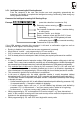

Reset Pushbutton:
The button can be pushed using a tool such as a match, pencil, etc. and has the following
functions:
• By pushing the button once during the GSM Gateway operation you reset the equipment.
The program is terminated and restarted. This function has no influence on the GSM
Gateway set-up stored in the GSM Gateway memory.
• By keeping the button pushed during the GSM Gateway power-on you enter a special
mode where you can load a new software version into the GSM Gateway. For details
refer to the “Control Software Upgrade“ chapter.
Antenna Connector:
On models 501061E and 501063E, this connector is not earthed! While the GSM Gateway
metal cover is connected with the protective socket wire and thus earthed (as Security
Regulations require), the GSM Gateway electronic circuits (on these models) are not
earthed. This is advantageous when a PC is connected to the GSM Gateway: by connecting
a PC to the RS-232C serial interface (see later) that is earthed to another ground potential
(another mains circuit), you earth the GSM Gateway electronic equipment through this PC
and data transmission is not interfered by a ground potential difference.
In that case, you
need no opto-coupler isolation of the serial port even if the PC is tens of metres
distant. This, of course, is possible only if the antenna connector does not get in touch with
the GSM Gateway cover or the earthing thereof to another ground potential.
On models 501100E and 501105E, whole electronics including antenna connector is
earthed (connected to PE pin of AC plug and to all parts of metallic cover).
SIM Card Holder:
To insert or replace your SIM card remove the upper cover face with a tool (crosshead
screwdriver No.1). This gives your SIM card a better protection against misappropriation.
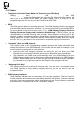
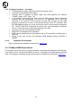
5.1.1. Bottom Cover Face
Telephone Line Connectors:
This model has two RJ-12 connectors: left one for PBX or phone, right one for PSTN line.
The telephone lines are connected to the central pair
of pins (two pins nearest to the connector axis). The
polarity is arbitrary. The electric isolation of the PBX
and GSM Gateway is located as follows:
• Always in PBX,
• During PSTN call, GSM Gateway is isolated from
PSTN line, which is physically interconnected to
PBX.
Mains Supply Connector:
The mains supply connector is used for PCs and is
thus identical in practically all countries. In all
countries, a power cable is used whose other end
(wall socket end) meets local regulations and socket
dimensions. The protective pin (in the middle) is
connected with the GSM Gateway cover and used
as the first over voltage protection stage for the
telephone line circuits. For security and functional
reasons, it is necessary that the pins earthed!
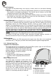
Fig. 8.: Bottom cover face:
1 - PBX line connector
2 – PSTN line connector
3 – AC mains connector
4 – RS-232C serial interface connector
28