ATEUS ® - DIAL-THRU GSM GATEWAY Ordering Nr. 501106E User Manual Version of manual: 1.0 Version of firmware: 2.
Dear customer, Let us congratulate you on purchasing our ATEUS ® - DIAL-THRU GSM GATEWAY. During the development and production of this product, care was taken to maximise its value, quality and reliability. We hope you will use the GSM Gateway to it full potential with long lasting benefits. ! Important ! • • • The manufacturer currently updates the firmware integrated into this product.
History Version What has changed or new in this version • 1.0 • • Common information taken from the ATEUS ® - GSM GATEWAY COMPACT 2000 manual, version 10.
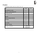
Checklist Packaging list, please check the contents of your unit: Item Quantity GSM Gateway 501106E 1 Mains (A.C.
Contents 1. Introduction .......................................................................................... 6 1.1. PURPOSE .......................................................................................................................... 6 1.2. HOW TO SAVE GSM CALL COSTS ....................................................................................... 6 1.3. OTHER ADVANTAGES AND APPLICATIONS ............................................................................ 6 1.4.
. Parameter Tables ................................................................................ 44 7.1. BASIC PARAMETERS ........................................................................................................ 44 7.2. PBX’S CO LINE INTERFACE PARAMETERS ......................................................................... 48 7.3. CALL SORTING TABLE ...................................................................................................... 50 7.4.
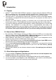
1. Introduction 1.1. Purpose • • • • ATEUS ® - DIAL-THRU GSM GATEWAY operates on single analog line between PSTN and PBX (or a telephone set, coin-operated automatic machines, etc.). It allows its users to make calls via the cheaper way, automatically switching between PSTN and GSM network. The voice mode, i.e. an outgoing or incoming call, is the basic function of the GSM Gateway. The Gateway is equipped with all functions necessary for this purpose and offers ease of use in this mode.
1.4.
2. Basic Installation Instructions This chapter describes the basic connection of the GSM Gateway that can be made in a few minutes. All you have to do is to connect an antenna, the power supply cable and telephone lines, insert your SIM card and the GSM Gateway is ready to work. 2.1. Proper Location • • • • • • • • • • • The ATEUS ® - DIAL-THRU GSM GATEWAY is a transmitter in principle.
2.2. Telephone and PSTN Line Connection 2.2.1. Connection to PBX Connect the ATEUS ® - DIAL-THRU GSM GATEWAY to external (C.O.) line of your PBX and to PSTN line socket, as shown on picture. If your PBX has more PSTN lines, make sure that outgoing calls to GSM will go out through this one or use more GSM gateways. Fig. 2.: Connection to PBX C.O.
2.2.2. Connection to Telephone Set (Answering Machine, Coin-Phone etc.) Connect the ATEUS ® - DIAL-THRU GSM GATEWAY to PSTN line socket and to your telephone set or some other terminal equipment. For convenience, you can add “ATEUS ® Ping pong” (intelligent double or triple branch made by 2N TELEKOMUNIKACE a.s., order Nos. 831127, 831128, 831137, 831138) to interconnect several devices, such as a telephone set and an answering machine; see Fig. 3.
2.3. External Antenna Connection Connect an antenna or an external antenna cable into the FME connector. The antenna location should have a good GSM signal. The antenna should be in the vertical position. For antenna and cable parameters refer to the “Technical Parameters”. Tighten an antenna connector gently by hand; do not use any tools! 2.4. SIM Card Set-up and Installation 2.4.1.
2.5. Power Supply Connection • Make sure that the voltage in your mains corresponds with the data on the product label. • Make sure that the antenna has been connected. If you connect a power supply to the equipment without the antenna, you might cause damage to the GSM module transmitter. • Connect your power cord. After a while, the green indicator “AC Supply O.K.” should go on. 2.6.
2.7. LED Indicators color, name green POWER green GSM yellow LINE yellow DATA red ERROR Description of statuses • lights = GSM module is powered • blinking slowly = GSM module is not powered (c.
3.1.2. GSM Gateway Ready Signalling The GSM Gateway registers the off-hook (current inflow). Immediately and then, if . Now the subscriber can everything is O.K., starts sending its usual dialling tone dial the number. Notes: • If GSM gateway needs PIN, special tone is transmitted. See chapter 3.9. Until the correct PIN is entered, GSM gateway will not allow any outgoing call. Only an incoming call from PSTN is allowed. • In some cases, PBX operates as a repeater.
3.1.6. Connection Making and Establishing In this moment, GSM gateway sends whole received number (or a number changed by “take away” and “append” parameters) to the GSM network. Next, GSM network is making a connection, and it takes typically 8 seconds. During this time, the subscriber hears a special "call progress" tone (differs by GSM gateway model and version of or software). Next, the subscriber usually hears the ringing tone another signal transmitted by the GSM network.
3.2.5. Call Routing According to a record found in the Call Sorting Table, call is routed to GSM or PSTN network or bared. If the required network is not accessible, GSM gateway starts to send busy tone or some special tone (PIN required etc.). Otherwise, the GSM Gateway transmits the received number into the right network. Description for the case of PSTN follows. 3.2.6. Connection Making and Establishing Remember that the PSTN line is already off hook (see chapter 3.1.2, last note).
3.3. Incoming Call 3.3.1. GSM Gateway Ringing, Extension Dialling, Extension Ringing and Connection Establishing When the GSM Gateway receives a command from the GSM network and, if available, the CLIP information, it starts ringing (i.e. generating the ringing voltage – whose timing is programmable) into the PBX. The PBX registers the ringing and then, one of the following situations may occur: 3.3.1.
3.3.4. Subscriber Disconnection (Power Down) If a subscriber blocks the GSM Gateway unnecessarily by not hanging up after the call, he or she will get the busy tone first and then is disconnected (Power Down status). 3.4. Begin and end of connection signalling Signalling by a current break or polarity change (see parameters 231 to 234) works differently in a case of GSM and PSTN call: GSM call: signals may be generated by GSM gateway, according to parameters 231 to 234.
3.7.1. Intelligent Incoming Call Routing Control From the viewpoint of the user, this function can work completely automatically but moreover it is possible to complete the Intelligent Incoming Call Routing Table during any call by special command: Command for Intelligent Incoming Call Routing fill-up: Example: (route this subscriber to extension 234) Extension number entering, or for command cancelling.
3.8. Telephone Line Tones, Ringing Course - Summary The ATEUS ® - DIAL-THRU GSM GATEWAY transmits tones to the telephone line that signal its operating status. The frequency is 425 Hz for all tones. Common Dial tone: • The equipment is registered in the domestic GSM network. • The equipment is ready to receive dialling. • This tone has the same parameters as the PSTN dial tone. • The parameters of this tone are programmable.
3.9. PIN/PUK Code Entering 3.9.1. Three Ways of PIN Code Entering With a common mobile telephone, you have to enter your PIN code after power-on in order to be protected against misappropriation (of your powered-off telephone) and misuse. With the GSM Gateway, this situation may occur after power failure. The difference is that there is often no one to know and enter the PIN code after power recovery.
3.10. Notes • Telephone Line Power Down (Model for External Line of PBX Only) , busy Dialling , PIN and PUK tones are transmitted into a line for 60s. When this time elapses, the line is put in the Power Down status (no power supply) until it is hung up. In the programming mode, the line is put in the Power Down after 180s. • DISA The DISA service relates to incoming calls only.
3.11. Instructions for Use for Common Users As previously mentioned, subscribers usually use their PBX and GSM Gateway intuitively without reading any instructions, or follow very simple instructions provided by an authorized person. These instructions may differ in details according to the PBX set-up. You can complete and copy the “aid“ included below for all users: Instructions for GSM Gateway Use GSM Gateway Calling: • Dial .......... before the number. • If you will hear the busy tone , try later.
4. User Manual – Description of Data Functions 4.1. Use of Data Mode 4.1.1. Destination: • For data transfer between two computers (second one can have whichever modem) • For connecting to Internet • High speed data (GPRS) mode can be used for connecting to Internet and similar applications (model 501105) 4.1.2. Serial interface Serial interface connector is D-Sub 9 pins, female, see fig. 9. It is connected like a common external modem. All handshake signals are used in data mode.
Important note: current version of firmware for GPRS model is not able to handle any voice calls during all time of GPRS connection (between ATD to ATH commands). Notes: • SMS can be transmitted and received during call. • SMS program reads all new SMS’s stored on SIM card right after start. SMS program automatically erases SMS’s from SIM card, if you don’t disable it. It is adding all new SMS’s to file on your PC. Almost unlimited number of SMS’s can be stored and viewed this way.
4.1.9. Serial port functions – for experts • If GSM gateway is ready, it will send back all commands (echo) • Connection is signalled by DCD output • Incoming data is signalled by RING output and GSM gateway will transmit: +CRING: +CLIP:””, 145 • It is possible to select after how many rings the GSM gateway should answer an incoming data call automatically. You can set it by parameter 181 or the ATS0 command.
5. Installation Instructions for Advanced Users ATTENTION! DANGER! Draw out an AC mains cord before opening a cover! Risk of an electric shock! WARNING! All removable parts of cover are earthed with earthing cables! We do not recommend that you disconnect these cables. If you do so, remember to reconnect all before closing the cover! This chapter describes primarily the connection of universal inputs and outputs, the serial interface and all situations that a technician may face during common servicing.
Reset Pushbutton: The button can be pushed using a tool such as a match, pencil, etc. and has the following functions: • By pushing the button once during the GSM Gateway operation you reset the equipment. The program is terminated and restarted. This function has no influence on the GSM Gateway set-up stored in the GSM Gateway memory. • By keeping the button pushed during the GSM Gateway power-on you enter a special mode where you can load a new software version into the GSM Gateway.
RS-232C Serial Interface Connector: Since the GSM Gateway in its data mode is a regular modem, the connector pins are exactly the same as in an ordinary modem, see Fig. 9. For the PC connection, a non-crossover (1:1) extension cable – the same as for the connection of a PC and external modem – is used. The maximum cable length is in excess of 30 metres and depends on the PC – it may be a little trial and error is needed to find an exact maximum length. Fig. 9.
5.2.
Explanatory Notes 1. LED indicators 2. TL1 - Reset pushbutton 3. Lithium battery in holder 4. SIEMENS ® GSM module TC35 or MC35 5. Mains transformer 6. PSTN line transformer 7. BJ1 - 2 x 10,000 A surge arrester – PSTN line first stage overvoltage protection 8. X6 – PBX line RJ-12 connector 9. X1 – PSTN line RJ-12 connector 10. X7 – mains supply connector 11. J2 – RS-232C serial interface connector 12. P1 - Mains fuse – T 200 m A 13. JP1 - diagnostic connector of power part 14.
5.3. Fuse Exchange General rules: • Use only a fuse of the same value and type. • Disconnect the AC power cable while replacing the fuse. • Fuse for AC power can be replaced only by service which is able to check such parameters as power consumption, DC voltages etc. • If a fuse fails again, manufacturer must repair equipment. 5.4. Lithium Battery Exchange ATTENTION! Explosion risk when the lithium battery is replaced incorrectly.
6. Programming 6.1. How to Program You can program your GSM Gateway in three ways: with a telephone, PC, or remote by PC as listed in the table below: Programming method: Programming: Phone Parameters with exception of I2CR table and SMS texts: PC PC, remote *) I2CR table and SMS texts: Reading of all parameters: Upgrade of GSM Gateway firmware: *) By reason of extended Call Sorting Table, only records 500 to 599 of this table are programmable by phone.
6.3. Handset-Based Programming 6.3.1. Requirements and Recommendations • • • You need another extension of the same PBX and a tone-dialling telephone set for programming. Use the telephone-based programming only if you do not want to set up many parameters. Remember that you do not have any feedback with a telephone! Complete the prepared form first – think before programming! 6.3.2. Entering Programming Mode • Pick up the handset. If you have a phone connected directly with GSM gateway, go to next step.
Programming Example: Sets the GSM Gateway clock at 12 o’clock, 30 minutes, 0 seconds. Important warning!!! While setting time parameters note the units they are set in – seconds or milliseconds. Since you cannot enter the decimal point from your telephone, milliseconds must be used wherever seconds are too rough. However, you cannot enter any number in the allowed interval (173 ms, e.g.), but you have to respect the step prescribed for the particular parameter. If one step is 100 ms, e.g.
6.3.5. Programming Error • If you make a mistake while entering a number (no matter whether a parameter number or a value) and find it before you press programming step using the , you can cancel the whole character. • If the GSM Gateway transmits a rejection signal parameter number even if the value was incorrect. • If, while programming more parameters at the same time (table line) using the above mentioned procedure, you make a mistake in the third parameter, e.g.
6.4. PC - Based Programming via serial interface 6.4.1. Connecting to PC, starting of GSM program Connect GSM gateway and your PC or notebook by RS-232C Serial Interface. Use an enclosed serial cable or another common 1:1 male/female serial cable. Run GSM program (actual version is available on internet). Program works without connected GSM gateway too (prearrangement of set-up, demo...). It has three basic functions, described below. 6.4.2.
6.5. Remote Programming by PC 6.5.1. Remote Supervision Purpose Remote supervision allows reading and changing the GSM gateway configuration remotely, thus saving time of servicing technicians enabling them to solve some problems remotely. For remote supervision, the same GSM software is used as for local setting using a serial interface. All features are absolutely identical with the exception of the GSM gateway firmware upgrade, which cannot be done remotely. 6.5.2.
6.5.3. What Is "Call-back" In case of normal supervision call, the calling party, i.e. the Supervision Centre covers data transmission costs. To avoid billing complications, the GSM gateway can establish remote supervision connection on the account of the client’s GSM gateway. It is the socalled call-back: 1. The Supervision Centre GSM gateway or modem “calls” the client’s GSM gateway. 2.
6.5.6. How to make GSM Gateway ready for Remote Supervision 1 2 3 4 5 7 6 8 11 9 12 10 1. Connect the GSM gateway to your PC and run the GSM program. 2. Switch into the on-line mode. 3. If the connection fails, select the correct serial port number in the ‘Setting’ menu. 4. Read the GSM gateway setup. 5. Open the ‘Service Parameters’ item. 6. Open the remote supervision parameter folder. 7. Make sure that remote supervision is enabled. If not, enable it. 8.
6.5.7. How to Run Remote Supervision 1 2 10 3 11 5 4 6 7 8 9 1. 2. 3. 4. 5. 6. 7. 8. Run the GSM program on the Remote Supervision Centre PC. Click on this icon to open the list of supervised GSM gateways. The list may include subfolders in multiple levels. Click on this key to create a subfolder. Click on this key to create a new item in the list. Enter client's name, company etc. here. Enter the respective GSM gateway telephone number here.
6.5.8.
6.5.9. Data Connection Problems GSM data transmission is different from analog CO line data transmission: it is necessary to specify in advance whether the case will be voice, data or fax connection. With the connection once established, the connection mode cannot be changed. Therefore, the calling party should select the required connection before establishing it and this information should get to the target GSM network operator through all networks involved.
7. Parameter Tables 7.1. Basic Parameters Min. Max. Def. PIN entering mode PIN – value Par. No. 101 102 0 4 dig. 1 8 dig.
Parameter Number for automatic dialling Time-out for automatic dialling Maximal time of outgoing call to GSM Maximal time of incoming call from GSM SMS centre number COM – Data mode COM – SMS mode Enable sending call information via COM Automatic data calls answering Par. No. 156 157 Your choice Remarks Min. Max. Def. 0 18 dig. 15 7 158 0 2550 0 159 0 2550 0 160 161 162 - 20 dig.
• Silence after dialling This parameter has no effect. It is used only for GSM gateway with TC35 modules up to firmware version 3.0. • Parameters for dialling supervision and intelligent incoming call routing Dialling end identification: If the GSM Gateway does not identify the end of the dialled number by any faster method (refer to the Call Sorting table), it waits for a pre-set timeout.
105 = Volume control option by +/- 6 dB from the GSM network. 106 = Disables roaming in frontier areas to prevent the GSM Gateway from registering, in the event of a fault in the own GSM network, in a GSM network of the neighbouring country. 107 = Disables all incoming calls. 108 = Displays the GSM signal intensity every 10 seconds. 109 = If SIM memory is full, oldest SMS will be erased when new one will come in – to enable receiving commands for switches.
7.2. PBX’s CO Line Interface Parameters Parameter Received dialling (DTMF / pulse) Time parameters for Make min., pulse dialling Break min., receiver Flash min. On-hook min.
235 and 245: Frequency of tariff pulses or signalisation pulse for begin and end of connection: 2 6 Other 12 kHz 16 kHz Reserved Notes to PBX CO Line Interface Parameters: It is very important not to interchange dialling receive and send parameters! Dialling send parameters meet the applicable standards; while dialling receive parameters must be set with a sufficient reserve to receive even considerably damaged dialling. This applies generally to both tone and pulse dialling modes.
7.3. Call Sorting Table 7.3.1. Purpose This table describes GSM Gateway‘s behaviour (during outgoing calls) somehow depends on the called number. Usually, it is not difficult to recognize, according to a few first digits (the prefix), an international call, mobile network call, special service call, emergency call, etc.
7.3.3. Table Structure and Parameter Ranges xxx1 xxx2 xxx3 xxx4 xxx5 xxx6 xxx7 xxx8 xxx9 xxx0 Par. Call call Number End End Initial Impulses Take No. Begin of Append number enable routing length # * tariff per [ms] away 0 or Max. 16 Max. 16 0 = no 0=GSM 0 = no 0 = no 0... 100 to 0 – 16 digits 0,3...16 501 digits 1= yes 1=PSTN 1= yes 1= yes ...255 999900 0...9, *, # 0...9, *, # ... ... ... ... ... ... ... ... ... ... ...
Remarks and Explanatory Notes to Parameters • If you program the GSM Gateway using a PC, on each line you can add a comment that is saved but not sent to the GSM Gateway. • The table has now 250 records; rows A01 to A98 and B01 to B54 are programmable only by PC. • Since the table is shared by several functions, the sorting must be detailed enough to cover all purposes: if, for example, pseudo tariff metering is used, calls with different cost have to be distinguished even if all of them are allowed.
Help for parameters: 5001 = This parameter can disable searching in the table. In this case, last row “Other” is used for all numbers. 5002 = This parameter can disable an use of a the column “Call enable”. In this case, all numbers can be enabled or bared by this parameter; but a fitting row is searched and the other parameters are used. 5003 = This parameter can disable an use of a the column “Call routing”. In this case, all calls can be directed to GSM or PSTN. It can be usual e.g.
7.3.4. Example of a Table Note: I’m sorry this example (GSM Gateway T- Mobile, location Czech republic, Prague) is not very helpful for other countries; better one is under preparation. xxx1 xxx2 xxx3 xxx4 xxx5 Begin of Call call Number End number enable routing length # 501x 0 yes PSTN yes 502x 02 no PSTN yes Par. No.
7.3.5. Call Sorting Table – Form for Your Needs xxx1 xxx2 xxx3 xxx4 NumBegin Call Call ber of enable routing length number 0 = no 0 = GSM 0,3... 1= yes 1= PSTN 16 599x xxx5 xxx6 xxx7 End # xxx8 xxx9 xxx0 End Initial Impulse Take App * tariff [ms] away end 0 = no 0 = no 1= yes 1= yes Other 55 0– 0- 255 999900 016 *) Your notes *) Max. 16 digits 0...
7.4. Intelligent Incoming Call Routing Table The Intelligent Incoming Call Routing (refer to the User Manual) allows the GSM Gateway to call a specific extension upon having found the caller’s number (CLIP) in the Intelligent Incoming Call Routing table. This saves the switchboard operator’s time and the calling party’s time and money. This is possible only during calls from GSM network. GSM gateway cannot receive CLIP form PSTN line.
Help for parameters: 6001 = Enables the Intelligent Incoming Call Routing according to the caller’s number if included in the Intelligent Routing table. 6002 = your own international prefix is used for the completion of the called number to be included in the Intelligent Routing table. 6003 = Defines the password for the "Forward this caller to extension ... next time” command. 6004 = Locked records (starting from the table beginning) are protected against overwriting and have priority. 7.5.
7.6. Service Parameters Parameter Par. No. Service password 901 Time Date HW version SW version Serial No. GSM module serial No. Password for upgrade No. I. 902 903 911 912 913 914 921 Password - Dial Restriction only 922 Password - lock to operator.
Commands for initialising: Basic parameters Interface for external line of PBX Interface for local line of PBX Universal inputs and outputs Call sorting table Intelligent Incoming Call Routing Table Parameters for "Dial-thru" model Operation monitoring and signalling Complete initialisation No. 991 992 993 994 995 996 997 998 999 Parameter Valid service password must be entered as a parameter as verification to avoid inadvertent initialisation e.g. when this function is entered by mistake.
8. Miscellaneous 8.1. Telephone Cost Saving Tips • Fill in Call Sorting Table carefully; keep it actual when operators come up with new prefixes. Remember that this model of gateway is a routing device. • Decide, depending on your call traffic, whether to purchase a more GSM Gateways. Best way is to use GSM gateways for all PSTN lines of your PBX. • Select the appropriate GSM tariff rate while purchasing your SIM card.
8.2. Trouble Shooting If, after the GSM Gateway’s power-on, all LED's are on (except for the 1st and 4th from the upper end), any the following situations has occurred: • If the GSM Gateway does not beep, you have probably pressed the RESET button during the power-on and the GSM Gateway is waiting for software reprogramming. • If the GSM Gateway gives a permanent tone, some inapplicable software has been loaded (for a different GSM Gateway model).
9. Technical Parameters GSM: GSM network type SIM card GSM phase II plug-in 3 V, „small“ 2 W / 900 MHz Transmitter power 1W / 1800 MHz Receiver sensitivity -104 dBm GPRS class (model 501105) class 8 Antenna: Frequency Impedance Power Antenna connector type Cable length 900 / 1800 MHz 50 Ω 2W FME (male) 3 to10 m or without cable Mains: 230V AC, tolerance: Power consumption Mains connector Lithium battery type 230 V±10%, 50 or 60 Hz Max.
63 Serial Interface: Interface type Connector Interface data rate RS-232C D-Sub 9 pins, female 19200 bit / sec Other: Dimensions (w/o connectors) Operating temperature Air humidity 150 x 150 x 55 mm 0°C to 45°C 5 to 95% Use the product as designed and manufactured and in accordance with these instructions for use. The manufacturer reserves the right to modify the product in order to improve its qualities. The ATEUS ® - DIAL-THRU GSM GATEWAY contains no environmentally harmful components.
©2004 2N TELEKOMUNIKACE a.s.- Prague, DR 1101 v.1.