User Instructions
Manuals
Brands
Pulsar Manuals
Equipment for IP cameras
SG64 6-port switch for 4 IP cameras
1
2
3
4
5
2
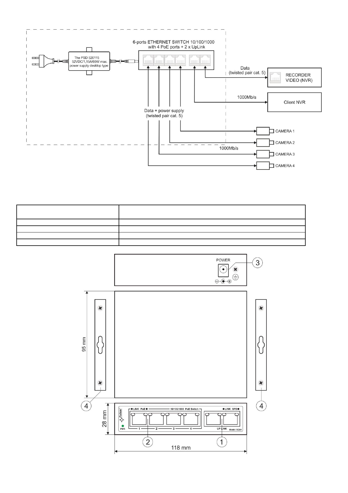
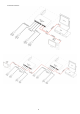
1.2
B
lock diagram.
Fig. 1. Block diagram
.
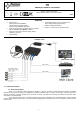
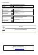
1.3. Des
cription of comp
onents and connectors.
Table 1. (
see Fig
.2)
Element no.
(Fig
. 2
)
Description
[1]
2
x
UP LINK port
[2]
4 x PoE port (1
÷4
)
[3]
Power Socket of the DC
[4]
Additional mounting elements
Fig
. 2
. The view s
witch'a.
1
2
3
4
...
5