
User Instructions

2
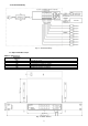
1.2. Schemat blokowy.
Rys. 1. Schemat blokowy.
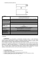
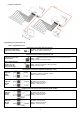
1.3. Opis elementów i złącz.
Tabela 1. (patrz rys. 2)
Element nr
(Rys. 2)
Opis
[1]
8 x PoE port (1÷8)
[2]
2 x UPLINK port (G1/TP, G2/TP)
[3]
2 x UPLINK port (G3/SFP, G4/SFP)
[4]
Gniazdo zasilania 52 V DC
[5]
Dodatkowe elementy montażowe
Rys. 2. Widok switch'a.