
User Instructions

3
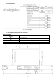
1.4. Technical parameters (table 2.)
Table 2.
Ports
8 x PoE (10/100 Mb/s) (RJ-45)
2 x UPLINK (10/100/1000 Mb/s) (RJ-45)
2 x UPLINK (10/100/1000 Mb/s) (SFP)
with connection speed auto-negotiation and MDI/MDIX Auto Cross)
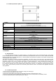
PoE power supply
IEEE 802.3af/at (1÷8 ports), 52 V DC / 30 W at each port *
Protocols, Standards
IEEE802.3, 802.3u, 802.3x CSMA/CD, TCP/IP
Forwarding rate
10BASE-T:14880pps/port
100BASE-TX:148800pps/port
Bandwidth
24 Gb/s
Transmission method
Store-and-Forward
Optical indication of
operation
Switch power supply
Link
PoE Status
Power supply
~100-240 V; 50/60 Hz; 1 A
the PSD 520175 52 V DC; 1,75 A /90 W max. power supply desktop type
Operating conditions
temperature -10°C ÷ 40°C,
relative humidity 20 % - 90 %, no condensation
Dimensions
W=220, H=44, D=150 [+/- 2 mm]
Additional equipment
plate to be fixed surface, bracket for RACK 19”
Net/gross weight
1,35 / 1,57 [kg]
Protection class
EN 60950-1:2007
I (first)
Storage temperatur
-20°C ÷ 60°C
Declarations
CE
* The given value of 30 W per port is the maximum value. The total power consumption should not exceed 80 W.
2. Installation.
2.1. Requirements.
The unit should be mounted in confined spaces, in accordance with the 2nd environmental class, with normal
relative humidity (RH=90 % maximum, without condensation) and temperature from -10°C to +40°C. Ensure the free flow
of air around the unit. The PSU shall work in a vertical position that guarantees sufficient convectional air-flow through
ventilating holes of the enclosure.
The switch load balance should be done before installation. The given value of 30 W per port is the maximum value
referring to a single output. The total power consumption should not exceed 80 W. The increased demand for power is
particularly evident in the case of cameras with heaters or infrared illuminators - when launching these features, the
power consumption increases rapidly, which may adversely affect the operation of the switch. As the device is designed
for a continuous operation and is not equipped with a power-switch, therefore an appropriate overload protection in the
power supply circuit should be provided. The electrical system shall be made in accordance with applicable standards
and regulations.
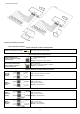
2.2. Installation procedure.
1. Connect switch to the PSD520175 52 V DC power supply unit desktop type.
2. Connect the power supply to the 230 V socket.
3. Connect the camera wires to the RJ45 connectors (PoE connectors (sockets RJ45 from 1 to 8).
4. Connect remain devices LAN to RJ45(G1/TP and G2/TP) connectors and SFP(G3/SFP and G4/SFP) sockets
5. Check the optical indication of switch operation (see Table 3).