
User Instructions

2
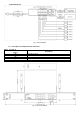
1.2. Block diagram.
Fig. 1. Block diagram.
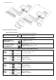
1.3. Description of components and connectors.
Table 1. (see Fig. 2)
Element no.
(Fig. 2)
Description
[1]
8 x PoE port (1÷8)
[2]
2 x UPLINK ports (G1/TP, G2/TP)
[3]
2 x UPLINK ports (G3/SFP, G4/SFP)
[4]
Power Socket of the 52 V DC
[5]
Additional mounting elements
Fig. 2. The view switch'a.