
User Instructions

2
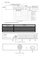
1.2 Block diagram.
Fig. 1. Block diagram.
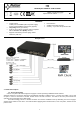
1.3 Description of components and connectors.
Table 1. (See Fig. 2, 3 and 4)
Component No.
(Fig. 2)
Description
[1]
LED indication
[2]
16 x PoE ports (1÷16)
[3]
2 x UP LINK ports (G1, G2)
[4]
Fan
[5]
Power Socket of the AC
[6]
Switch of mode Long Range
[7]
Additional mounting elements
Fig. 2. The front power of the switch.
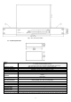
Fig. 3. Rear panel of the switch.