
User Instructions

2
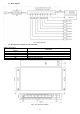
1.2 Block diagram.
Fig. 1. Block diagram.
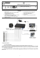
1.3 Description of components and connectors.
Table 1. (See Fig. 2)
Component No.
(Fig. 2)
Description
[1]
8 x PoE ports (1÷8)
[2]
2 x UP LINK port
[3]
Power Socket of the DC
[4]
Additional assembly elements
[5]
Switch of mode Long Range
Fig. 2. The view of the switch.