
User Instructions

www.pulsar.pl RSGUPS108 RACK POWER
8
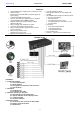
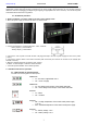
3.2. Optical indication of the switch operation:
OPTICAL INDICATION OF THE SWITCH's POWER SUPPLY
GREEN LED LIGHT (Power)
Indication of the switch's power
supply
OFF – no power supply of the switch
ON – power supply on, normal operation
OPTICAL INDICATION OF THE SWITCH's POWER SUPPLY (1÷8)
GREEN LED LIGHT (PoE)
Indication of the PoE power
supply at the RJ45 ports
OFF- no power supply at the RJ45 port (the device is not connected or not compliant
with the IEEE802.3af/at standard)
ON – supply at the RJ45 port
Blinking – short-circuit or output overload
YELLOW LED LIGHT (LINK)
The connection status of LAN
devices, 10/100/1000 Mb/s
and data transmission
OFF- no connection
ON - the device is connected; 10/100/1000 Mb/s
Blinking – data transmission
OPTICAL INDICATION AT THE UP LINK PORT
GREEN LED LIGHT
OFF- no connection or device connected /the device is connected 10/100 Mb/s
ON – the device is connected 1000 Mb/s
YELLOW LED LIGHT (LINK)
The connection status of LAN
devices, 10/100/1000 Mb/s
and data transmission
OFF- no data transmission
ON - the device is connected: 10/100/1000 Mb/s
Blinking – data transmission
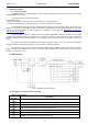
3.3. Technical output.
The power supply is fitted with the ALARM output of collective failure (relay type). A collective failure can be
triggered by the following events:
- 230 V mains power failure
- Failure of the switch mode power supply
- Too high temperature of the switch mode power supply (>70 °C)
- Low battery voltage (<23 V)
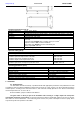
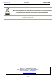
Fig. 5. Electrical diagram of the ALARM collective output of failure.
CAUTION! In Fig.5 the set of contacts shows a potential-free status of the relay, which corresponds to
power supply failure.
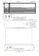
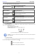
3.4. Acoustic indication.
A collective failure is indicated by the piezoelectric indicator, 1 beep every second. The acoustic indication can
be turned off by changing the ON / OFF position of the switch .
switch in the up position, indication ON
switch in the down position, indication OFF