
User Instructions

www.pulsar.pl RSGUPS108 RACK POWER
7
As the PSU is designed for a continuous operation and is not equipped with a power-switch, therefore an
appropriate overload protection shall be guaranteed in the power supply circuit. Moreover, the user shall be informed
about the method of unplugging (usually through assigning an appropriate fuse in the fuse-box). The electrical system
shall follow valid standards and regulations.
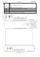
2.2. Installation procedure.
1. Before installation, cut off the voltage in the 230 V power-supply circuit.
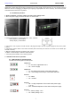
2. Mount the power supply in a RACK 19" cabinet as shown below:
- Mount M6 cage nuts
- Secure the enclosure with 4xM6 screws
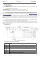
3. Connect the batteries in series/parallel to the + BAT- terminals:
- battery output (+): terminal BAT+
- battery output (-): terminal BAT-
4. Connect the ~230 V power cord with the IEC C13 plug (included) to the 230 V power supply and turn on the power
(~230 V).
5. Connect the camera cables to the RJ45 connectors (PoE connectors) and connect the recorder to the network (the
UPLINK connector).
6. Make the following technical connections when needed:
- ALARM – technical output of collective failure indication
7. Check the optical indication of the switch operation.
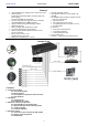
3. Indication of the device operation.
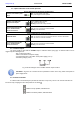
3.1. LED indication of operating status.
The PSU has 5 LED lights at the front panel:
GREEN LED:
on – the PSU is supplied with 230 V
off – no 230 V supply
GREEN LED:
on – DC voltage at the output of the switch mode PSU
off – no DC voltage at the output of the switch mode PSU
RED LED:
on – failure
off – no failure
RED LED:
ON – too high temperature of the switch mode power supply
(>70 °C)
OFF – standard temperature of the switch mode power supply
RED LED:
on – battery voltage <23 V
off – battery voltage >23 V